Overview
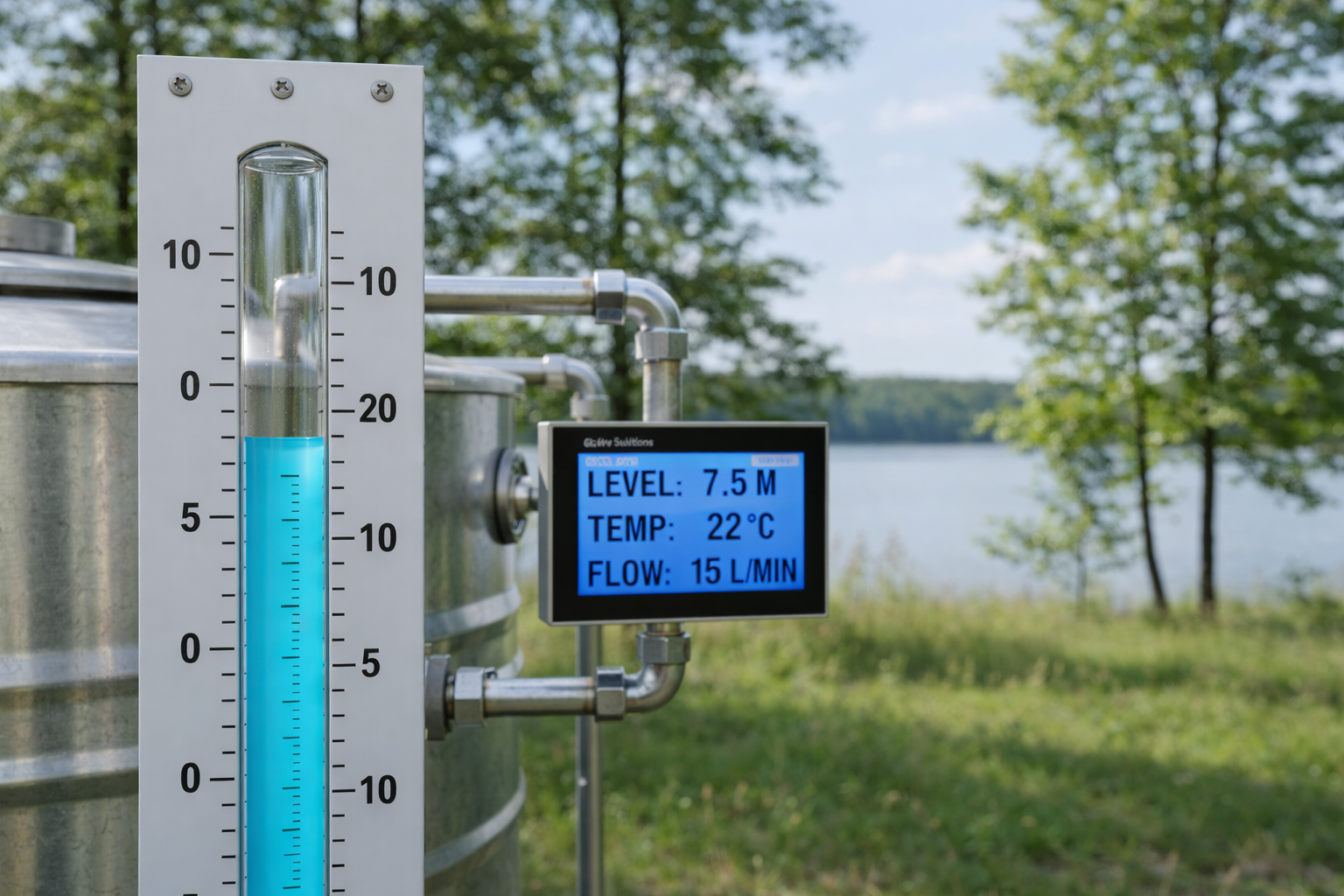
In this lesson, you will build a simple Water Level Indicator System using the RGX Kit. The system measures the water level using an analog water sensor and displays the reading on an LCD screen. To ensure safety, an LED will turn ON when the water level is low and turn OFF when the level is sufficient.
This project is inspired by real-world water monitoring systems used in:
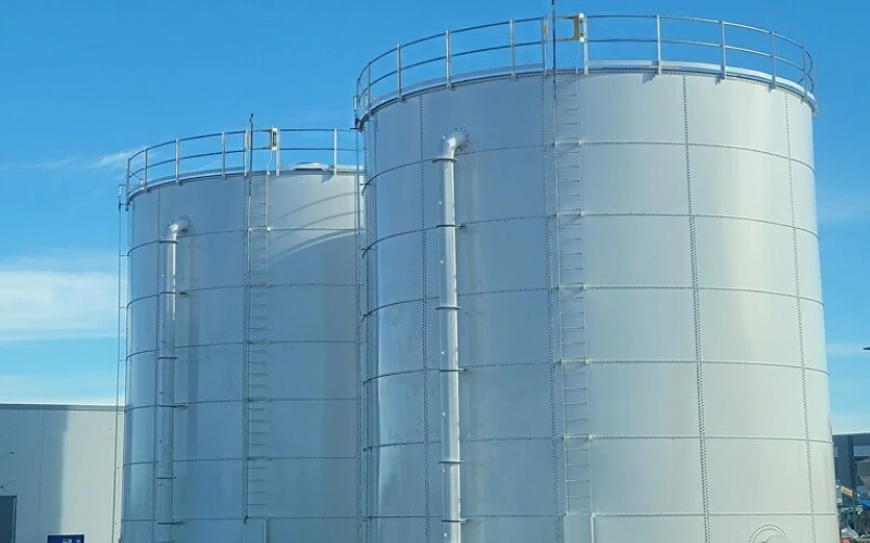
Water Tanks
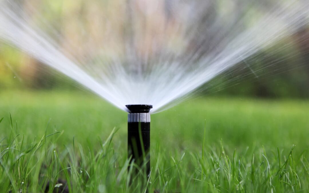
Irrigation Systems
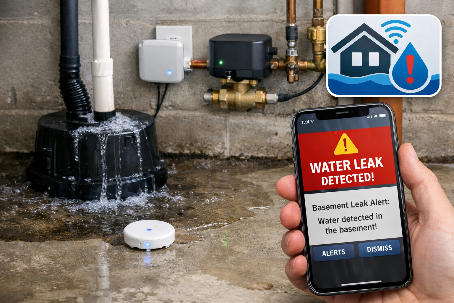
Smart Homes
Objectives
•
How an analog water sensor measures water level
•
How to read analog values using the RGX board
•
How to display real-time data on an LCD (1602 I2C)
•
How to use IF / ELSE logic for decision making
•
How sensors, displays, and indicators work together
Meet the Components
You will use:
•
Water Level Sensor
•
LCD Module
•
LED Module
•
RGX Control Board
•
RJ11 Easy-Plug Cables
Hardware Connections
Component | Pin Connection |
|---|---|
Water Sensor | A7 |
LCD | SCL/SDA |
LED Module | PIN 8 |
Make sure all connections are secure using RJ11 cables.
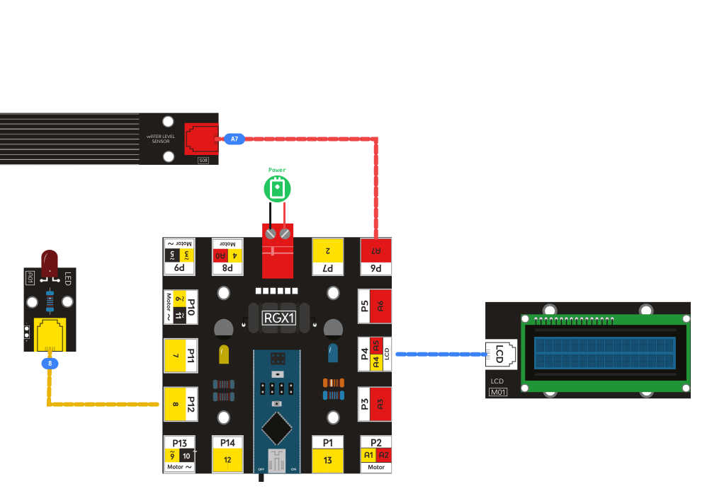
RGX connection
System Logic
The sensor provides a numerical value based on how much water is touching its surface. The RGX board processes this "analog value" to control the light.
Water Level Value | LED Status |
|---|---|
Less than 200 | ON (Low Water Warning) |
Greater than or equal to 200 | OFF (Water Level OK) |
•
Analog Sensing: The water sensor outputs a signal to PIN A7.
•
Visual Display: The LCD shows the live "waterValue" so the user can see the exact level.
•
Warning System: The LED acts as a visual alert when the tank is nearly empty.
Coding the System
Step 1: Declare Global Variable
1. Creates a global variable named waterValue.
2. Reads the analog value from PIN A7 (water sensor).
3. Stores the sensor reading inside waterValue.

Variable stored
Block Configuration
Setting | Value |
Variable Name | waterValue |
Data Type | int |
Initial Value | 0 |
Step 2: LCD Setup
Condition: Setup LCD 1602 mylcd address 0x27 SCL PIN# SCL SDA PIN# SDA
Action: 1. Initializes the LCD screen.
2. Set the LCD I2C address to 0x27.
3. Connects LCD communication lines: SCL → SCL SDA → SDA
4. Prepares the LCD to display data.
Step 3: Display Text on LCD
Action: Line 1: Displays the fixed text "WATERVALUE."
Line 2: Displays the current value stored in waterValue.
The LCD updates continuously, showing the real-time water level.
Step 4: IF – Low Water Level
Action / Function: Check if the water level value is less than 200. This means low water level. Turn ON the LED . Acts as a warning indicator.
Step 5: ELSE – Water Level OK
Action: Check if the water level is greater than 200. This means the water level is sufficient. Turn OFF the LED on PIN 2. The system returns to a normal state.
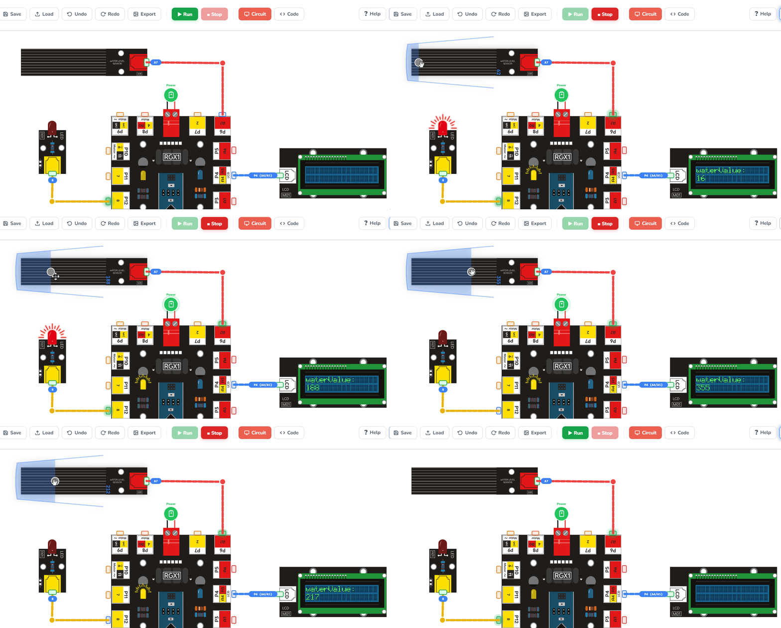
Running the code
Test Your System
Power the RGX board.
Experiment: Gently touch the water sensor with a damp cloth or dip it into a cup of water at different depths.
Observe: The LCD should show the numbers increasing as more water touches the sensor.
•
The LED should turn ON when the sensor is dry or barely wet (< 200).
•
The LED should turn OFF once the level reaches 200.
If this happens, your system is working correctly.
Improve & Extend
Try upgrading your water level system:
•
Audio Alert: Add a buzzer that beeps when water is low to grab attention.
•
Smart Pumping: Connect a water pump to fill the tank automatically when the level drops.
•
Text Feedback: Update the LCD to display "LOW WATER" or "TANK FULL" based on the measurement.