
Overview
In this lesson, you will build an autonomous vehicle that can follow a black line on a white surface using IR sensors and the RGX Kit.
You will explore how Infrared (IR) sensors function as digital inputs to "see" the floor and how the RGX board uses output signals to control DC motors. The lesson introduces the logic of automated transport systems, showing how a robot can make its own decisions based on the data it receives.
By following these steps, you will learn to connect sensors and motors, write a control program, and observe how a smart system interacts with its environment to navigate a path.
Objectives
•
How IR sensors work as digital inputs to detect surfaces.
•
How to control DC motors (the "muscles") using motor ports.
•
How the motor driver translates code into high-power movement.
•
How to implement logic to create an autonomous system.
Meet the Components
You will use:
•
2x IR Line Tracking Sensors (The Eyes)
•
2x DC Motors (The Muscles)
•
RGX Control Board (The Logic/Motor Driver)
•
RJ11 Easy-Plug Cables
Hardware Connections
Component | Pin Connection |
|---|---|
Line Tracking Sensor | Digital Pin A1 |
Left Motor (M1) | Digital Pin 9 (via Driver) |
Right Motor (M2) | Digital Pin 3 (via Driver) |
Ensure the Motor Driver is connected to a power source to provide enough energy for the DC motors.
Make sure all connections are secure using RJ11 cables.
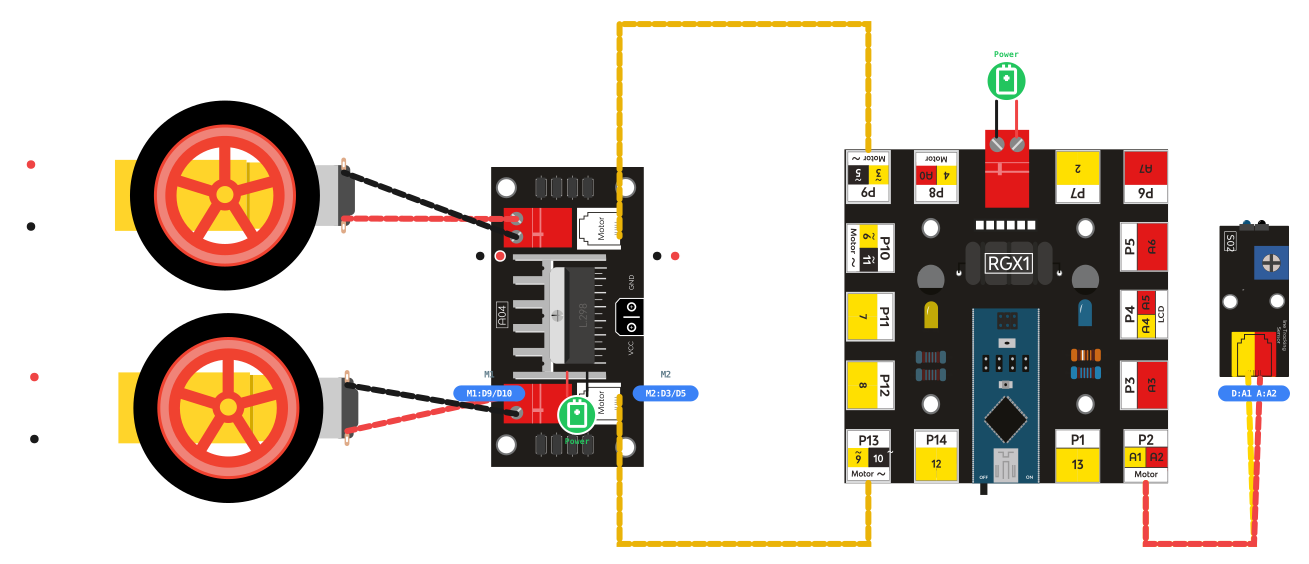
RGX connection
Understanding Input and Output Pins
The RGX board acts as the "brain" of your vehicle, communicating through specific pins and ports.
Input Pins (The "Eyes")
The IR Line Tracking Sensor
An IR sensor measures reflection. It sends out infrared light; if it hits white, the light bounces back (LOW). If it hits black, the light is absorbed (HIGH). By switching between these two states, the robot stays on the edge of the path.
State | Surface | Meaning |
LOW (0) | White Floor | Path is clear / No line detected |
HIGH (1) | Black Line | Line detected / Trigger correction |
Output Pins/Ports (The "Muscles")
The Motor Driver (L298)
The RGX board cannot provide enough current to spin heavy motors directly. The motor driver acts as a gateway. It takes low-power signals from Pins 9 and 3 and switches high-power battery current to the motors.
Controlling Motor Direction
DC motors change their rotation based on the direction of electricity flow:
•
Move Forward: Connect the motor wires as shown in the diagram (Red to Positive, Black to GND).
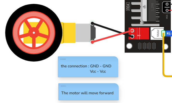
forward
•
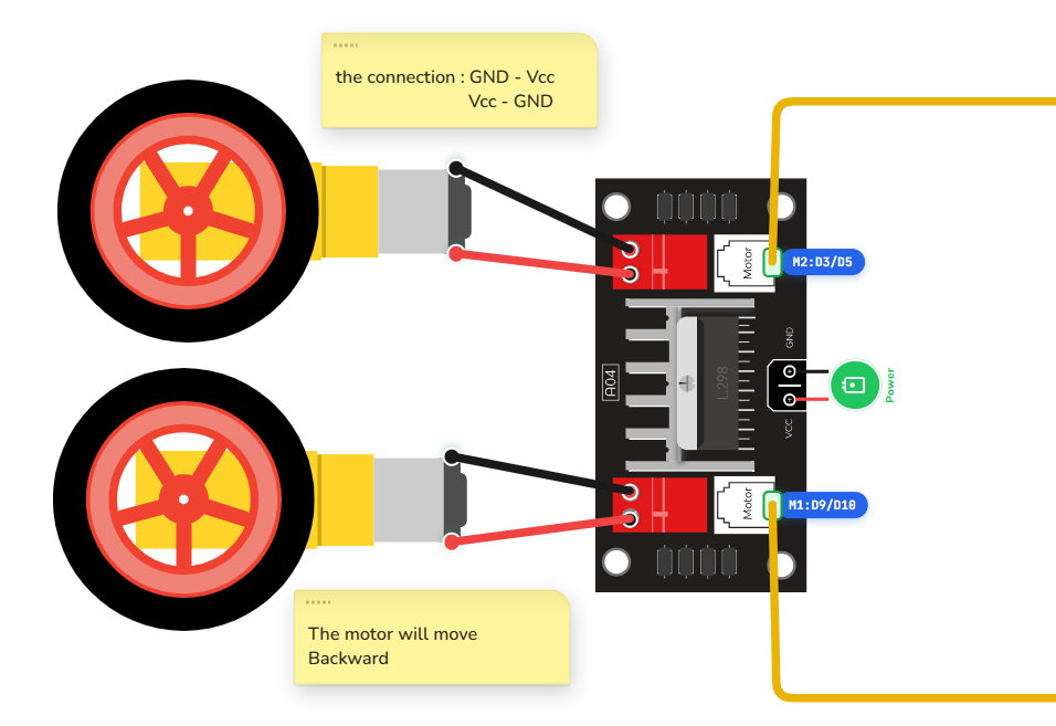
Move Backward: If you swap the connections (Red to GND and Black to Positive), the motor will spin in the opposite direction.
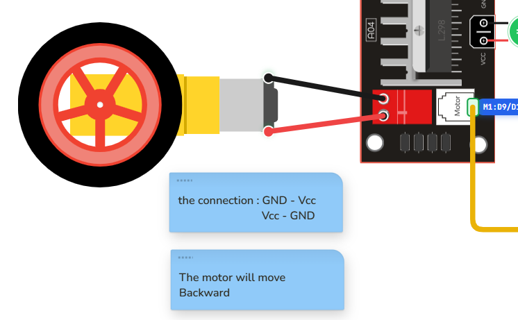
backward
Coding the System
Manual Control: How to Move
Before tracking a line, you must learn how to move your "muscles." In the RGX system, we use analogWrite(pin, speed) to control the power.
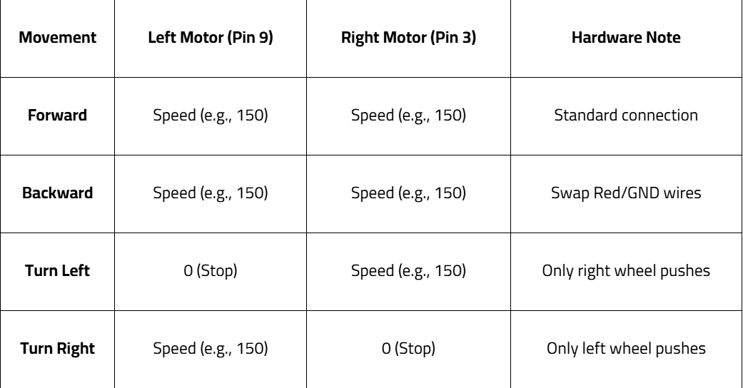
Step 1: Initialize the Sensors and Motors
Condition: Setup Pin A1 as INPUT. Setup Pins 9 and 3 as OUTPUT. Actions:
Use pinMode to set the component states:
•
Initialize the sensor to "listen."
•
Initialize the motor pins to "speak" or send power.

Step 2: Read and Verify
Before writing logic:
•
Create a variable called "value" to store the sensor data.
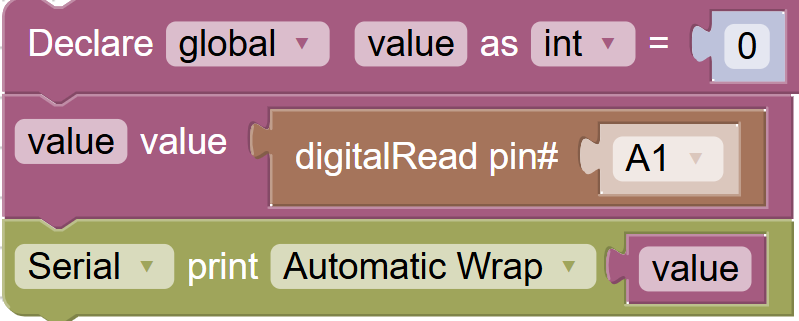
Use digitalRead(A1) to save the surface state into the value variable.
Use the Serial Monitor to verify your sensor.
•
Surface: White Floor -> 0
•
Surface: Black Line -> 1
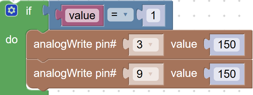
Step 3: Programming Forward Movement
Condition: Make the robot move straight.
Actions:
•
Use analogWrite to set Pin 9 to 150.
•
Use analogWrite to set Pin 3 to 150.
Step 4: Programming Backward Movement
Condition: Make the robot move in reverse.
Actions:
•
Hardware Action: Swap the Red and GND wires for both motors.
•
Code Action: Use analogWrite on Pins 9 and 3 at speed 150.
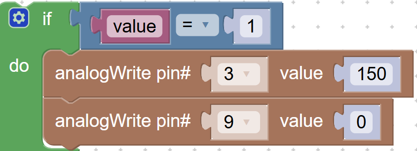
Step 5: Programming Turns (Left or Right)
Condition: Change direction.
Actions:
•
To Turn Left: Set Pin 9 to 0 and Pin 3 to 150.
•
To Turn Right: Set Pin 9 to 150 and Pin 3 to 0.
Pro Tip for Steering: To make your robot smarter at turning, you can eventually add two line tracking sensors—one for the left side and one for the right side—to detect exactly which way the line is curving!
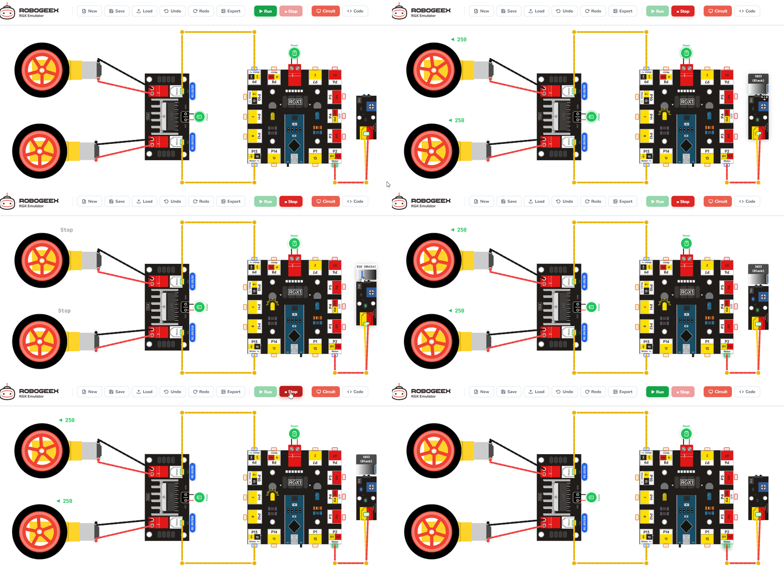
Backward
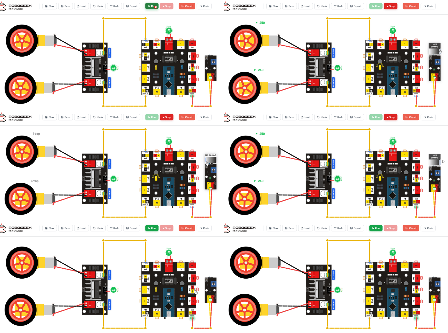
Forward
Test Your System
1.
Place your robot on the track in the emulator.
2.
Run the code.
3.
If the robot spins in circles, swap the motor wire directions in the code or ports.
4.
If the movement is too fast, lower the motor speed (e.g., try 100 instead of 150).
Improve & Extend
Try upgrading your autonomous vehicle:
•
The Finish Line: Add logic to make the robot stop if both sensors see black at the same time.
•
Precision Mode: Create a variable to slow the speed down automatically when a turn is detected.
•
SDG Innovation: How could this system be used in real-world factories to transport goods (SDG 9)?