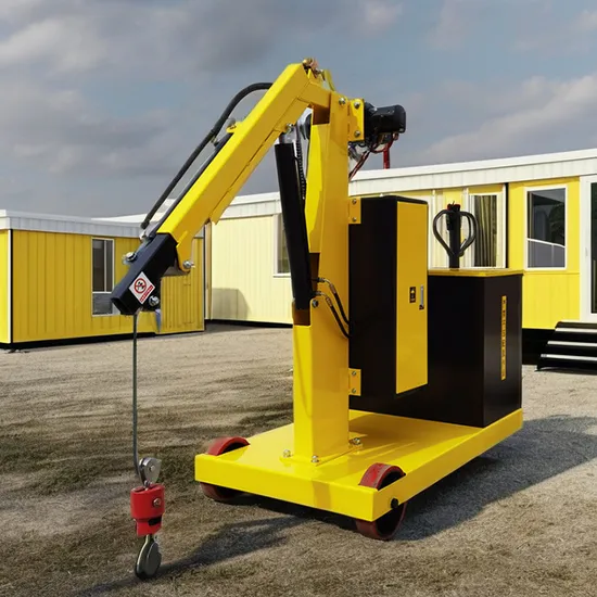
Overview
In this lesson, you will unlock the "Superpower" of microcontrollers: Data Translation. You will build a Smart Crane Control System that uses a Potentiometer to guide a Servo Motor with pinpoint accuracy.
The challenge? Your Potentiometer speaks a language of large numbers (0–1023), but your Servo Motor only understands angles (0–180).
You will master the Map Block—the ultimate math translator that makes these two completely different components talk to each other perfectly!
Objectives
•
Master the Map Block to convert sensor data between different scales.
•
Understand the relationship between input ranges and output limits.
•
Learn how to control a Servo Motor for precise physical movement.
•
Explore how "Mapping" is used in everything from volume sliders to robotic surgery.
Meet the Components
You will use:
•
Potentiometer Module (The Input)
•
Servo Motor (The Actuator)
•
RGX Control Board
Hardware Connections
Component | Logic Role |
|---|---|
Potentiometer/PIN A6 | The "Input" (0-1023) |
Servo Motor/PIN 12 | The "Output" (0-180) |
Make sure all connections are secure using RJ11 cables
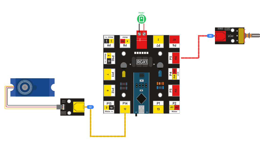
RGX connection
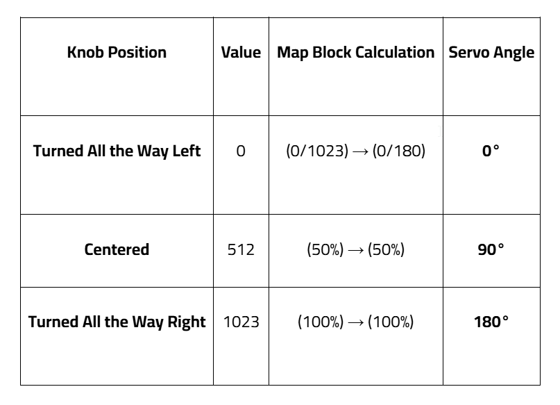
System Logic: The Translation Table
The system constantly reads the knob, passes the number through the "Mapper," and sends the result to the motor.
Coding the System
The Star of the Show: The Map Block
The Map Block is like a high-speed translator living inside your RGX board. It solves the biggest problem in electronics: scale incompatibility.
The Problem: Why not use IF blocks?
Imagine trying to control the Servo without a Map block. You might try to write logic like this:
•
If value is 0, set angle to 0.
•
If value is 10, set angle to 2.
•
If value is 50, set angle to 8...
To get smooth movement, you would need to write over 1,000 lines of code! This would make your program extremely long, difficult to read, and almost impossible to fix.
•
The Scale Gap: The Potentiometer range (0 to 1023) is nearly 6 times larger than the Servo range (0 to 180).
The Solution: "Mapping"
Instead of writing thousands of lines of logic, we use the Map Block. It uses a mathematical formula to calculate the relative position instantly.
•
If the input is at 0% (Value: 0): Map outputs 0.
•
If the input is at 50% (Value: 512): Map outputs 90.
•
If the input is at 100% (Value: 1023): Map outputs 180.
The Magic Formula:

Map Block
Step 1: Initialize Variables
Action: Declare two variables:
1.
KnobData(int): To store the raw number from the Potentiometer.
2.
mappedAngle (int): To store the translated result from the Map Block.

Initialize Variables
Step 2: Use the Map Block

mapped Block
Set mappedAngle = Map(knobData)
•
From Low: 0 | To High: 1023
•
From Low: 0 | To High: 180
1.
Read Analog PIN A7 and save to knobData.
2.
Find the Map Block in the Math category.
Step 3: Command the Servo
Action: Use the Servo PIN# block (Actuator category).
Set PIN 12.
Input the mappedAngle variable as the degree.
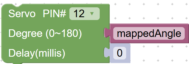
servo block
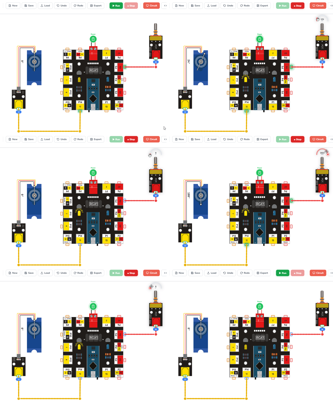
Running the code
Test Your System
1.
Power up!
2.
Slow Turn: Rotate the knob slowly. Notice how the servo follows every micro-movement of your hand.
3.
Boundary Test: Turn the knob to its absolute limits. Does the servo stop exactly at its 0 and 180 limits without vibrating?
Improve & Extend
•
Reverse Logic: Change the Map Block to To Low: 180 and To High: 0. Now, turning the knob right moves the motor left!
•
Dead Zones: Change the Map range to 0 to 90 to limit the crane's movement to a quarter-circle.
•
LCD Dashboard: Display the "Raw Value" vs. the "Mapped Angle" on an LCD to see the math in action.