Overview
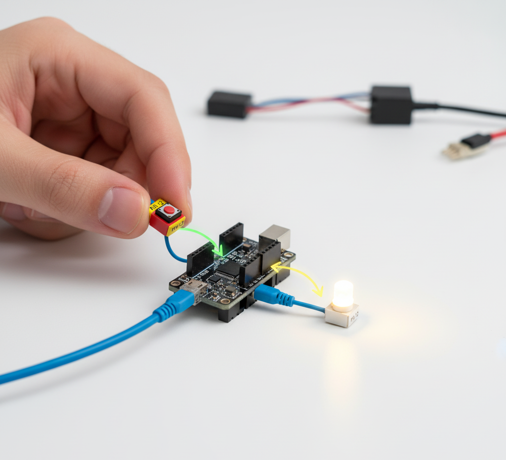
In this lesson, you will build a simple lamp control system using a push button and the RGX Kit.
You will explore how a button functions as a digital input and how the RGX board uses output signals to control an LED lamp. The lesson introduces the basics of digital signals, which operate using two states: LOW (0) and HIGH (1).
By following the steps independently, you will connect the components, write a simple program, and observe how the system reads input from the button to turn the lamp ON or OFF. This activity helps you understand how inputs and outputs work together in a simple smart system.
Objectives
•
How a button works as a digital input
•
How to control a lamp (LED module)
•
How inputs and outputs interact in a simple smart system
Digital Signals
Before building the lamp control system, it is important to understand digital signals, because the RGX board communicates using digital values.
Digital signals are the basic language used by computers and microcontrollers.
Instead of using many voltage levels, digital systems use only two states.
•
LOW
•
HIGH
These two states represent the numbers 0 and 1, which are the foundation of digital electronics.
Digital Signal
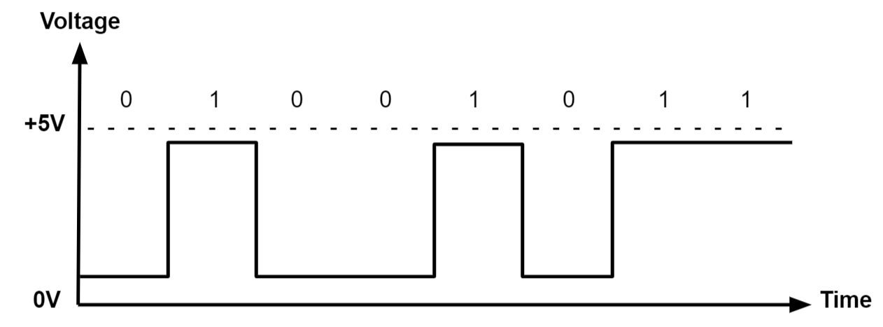
This diagram shows how a digital signal changes over time.
In this graph:
•
The vertical axis represents voltage.
•
The horizontal axis represents time.
When the signal is at 0 volts, the system reads it as 0 (LOW).
When the signal rises close to 5 volts, the system reads it as 1 (HIGH).
When the signal rises close to 5 volts, the system reads it as 1 (HIGH).
This switching between LOW and HIGH is how digital devices send information.
Digital State Meaning:
The controller interprets voltage levels as logical states.
State | Volt | Mean |
|---|---|---|
LOW | 0V | OFF / False / 0 |
HIGH | 3.3–5V | ON / True / 1 |
Example interpretations:
•
If a button sends HIGH, the RGX board knows the button is pressed.
•
If a button sends LOW, the RGX board knows the button is not pressed.
Understanding Input and Output Pins
The RGX board communicates with external components using pins.
Pins are the connection points that allow the board to send and receive signals.
Pins are the connection points that allow the board to send and receive signals.
There are two main types of pins used in this project:
•
Input Pins
•
Output Pins
These are often called "I/O pins," which stands for "input / output."
Input Pins
An input pin is used to receive information from a component.
Example in this project:
•
The button module sends a signal to the board.
•
The board reads that signal using a PIN #.
When the button is pressed, the pin reads:
HIGH (1)
When the button is not pressed, the pin reads:
LOW (0)
So the input pin is used to detect what is happening in the system.
Output Pins
An Output Pin is used to send signals to other components.
Example in this project:
•
The board sends a signal from PIN # to the LED lamp.
When the pin sends
•
HIGH → the lamp turns ON
•
LOW → the lamp turns OFF
So the output pin is used to control devices.
Meet the Components
You will use:
•
Button Module
•
LED Module (Lamp)
•
RGX Control Board
•
RJ11 Easy-Plug Cables
Hardware Connections
Component | Pin Connection |
|---|---|
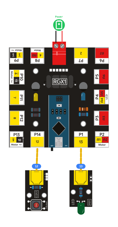
Button Module | Digital Pin 12 |
LED Lamp Module | Pin 13 |
Make sure all connections are secure using RJ11 cables.
RGX connection
Input and Output in Your System
Your system uses one input and one output.
Component | Purpose |
|---|---|
Button Module PIN 12 | Sends signal to the board (Input) |
LED Lamp PIN 13 | Receives signal from the board (Output) |
System Signal Flow
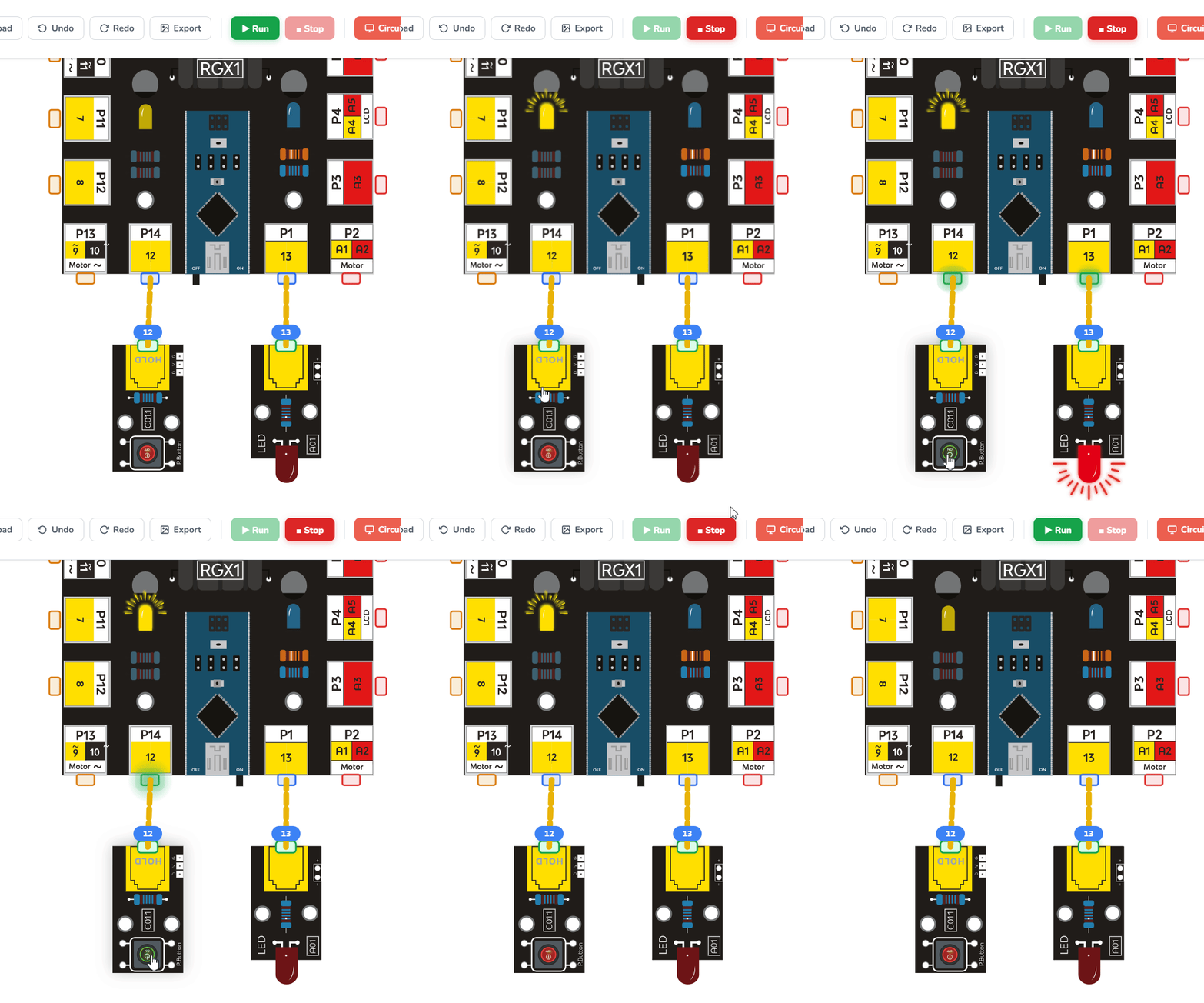
The system follows a simple flow:
Button → RGX Board → Lamp
(Input) (Process) (Output)
controlling LED
•
Input: The button sends a signal when it is pressed or released.
•
Process: The RGX board reads the signal using an input pin and processes the button state.
•
Output: The board sends a command through an output pin to control the lamp.
Coding the System
Step 1: Read the Button
First, create a simple program that reads the button state.
The button is connected to PIN 12.
The board reads the signal as a digital value:
•
HIGH → Button is pressed
•
LOW → Button is not pressed
You can use Serial Print to display the button state and verify that the button is working.
When you press the button, the message should appear in the serial monitor.
Step 2: Add a Small Delay
Because the loop runs thousands of times per second, the board may send messages too quickly to read.
To slow things down, add a Delay block inside the loop.
A delay tells the board to pause the program for a short time before repeating the loop.
For example:
Delay 200 ms
This means the program waits 0.2 seconds before checking the button again.
This makes the output easier to observe.
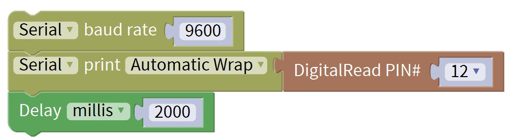
Mixly code
Step 3: Control the Lamp
Now connect the LED lamp module to PIN 13.
Update the program so that the lamp reacts to the button state.
•
If the button sends HIGH, turn the lamp ON
•
If the button sends LOW, turn the lamp OFF
The button now acts like a simple light switch.

Test Your System
Power the RGX board.
Press the button → the lamp turns ON
Release the button → the lamp turns OFF
Release the button → the lamp turns OFF
If this happens, your system is working correctly.
Improve & Extend
Try upgrading your button-controlled lamp:
•
Add a buzzer when the lamp turns ON
•
Add a delay before the lamp turns OFF