Overview
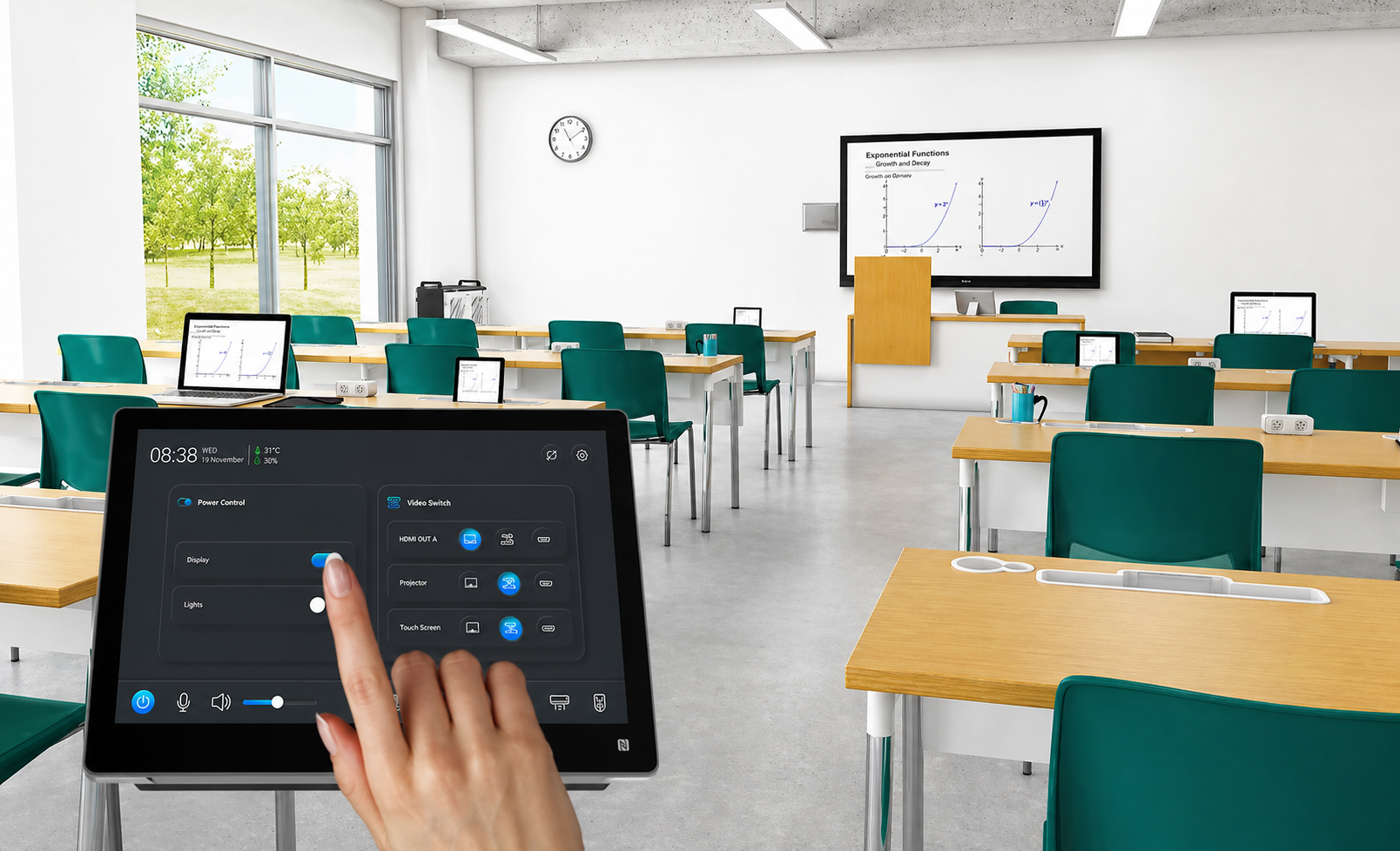
In this lesson, you will build a Classroom Control System using the RGX Kit. You will use an IR Remote to wirelessly control multiple devices—including servos, lights, and alarms—simulating a real-world smart classroom environment.
Objectives
•
Apply your knowledge of Infrared (IR) communication to handle multiple unique commands.
•
Control multiple Servo Motors and LEDs simultaneously.
•
Understand how to use Switch-Case Logic to organize complex button mapping more efficiently than if-else blocks.
Meet the Components
You will use:
•
IR Receiver Module
•
IR Remote Control
•
Servo Motor
•
LED Module
•
Buzzer
•
FAN
•
RGX Control Board
•
RJ11 Easy-Plug Cables
Hardware Connections
Component | PIN Connection |
IR Receiver | Digital PIN2 |
Servo Motor 1 | PIN 13 |
LED Module | PIN 8 |
FAN | PIN 7 |
Buzzer | PIN 12 |
Make sure all connections are secure using RJ11 cables.
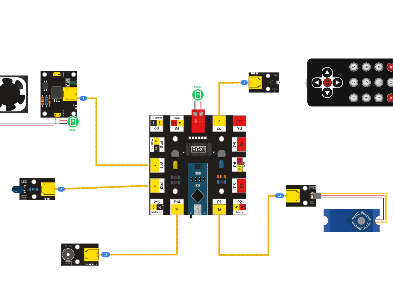
RGX connection
System Logic
The system constantly waits for a signal from the IR remote. Each button on the remote sends a unique IR code . When a specific code is received:
•
A servo moves
•
A light turns ON or OFF
•
A buzzer sounds
•
A FAN turns ON or OFF
Remote Status | Action |
Button1 | Open Servo |
Button2 | LED ON |
Button3 | FAN ON |
Button4 | Buzzer ON |
Button5 | All off |
This allows full classroom control without touching the devices .
Coding the System
💡 Tech Logic: Why use a Switch Block?
Until now, we have used If-Else blocks to make decisions. Think of an If-Else chain like a long line of doors in a hallway. To find the right room, you have to stop and knock on every single door:
•
"Is this Room 1?" No.
•
"Is this Room 2?" No.
•
"Is this Room 3?" Yes!
As your project grows (like adding a Fan, LED, and Buzzer), that hallway gets very long! A Switch Block is like an Elevator. Instead of checking every floor, you press the button for "Floor 3" and the system jumps directly there.
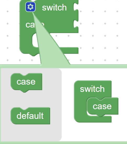
switch blcok
The Benefits:
•
Cleaner Code: Your program is much easier to read and doesn't look like "spaghetti."
•
Faster Processing: The computer doesn't waste time checking conditions that don't match.
•
Organization: All your "Cases" (Button 1, Button 2, etc.) are neatly grouped in one place.
How to read the block:
1.
Switch (ir_item): This tells the computer, "Look at the value stored inside the variable ir_item."
2.
Case (16724175): This says, "If the value is exactly 16724175, do the following action."
3.
Default: This is the "Safety Case." If the code doesn't match any of your buttons, the computer follows the instructions here.
Follow the structure below to build your program:
Step 1: Setup IR Input
Use the IR Receive block.
•
Set the variable name to ir_item.
•
Open the Serial Monitor to verify your remote's unique codes.
Step 2: The Switch Block
Instead of stacking multiple If blocks, use one Switch block targeting the ir_item variable.
Case 0xFFA25D: Set Servo PIN 4 to 180 (Open).
Case 0xFF629D: DigitalWrite LED PIN 7 to HIGH.
Case 0xFFE21D: DigitalWrite Fan PIN 12 to HIGH.
Case 0xFF22DD:Play Tone on Buzzer PIN 8.
Case 0xFF38C7: Turn OFF all components .

code
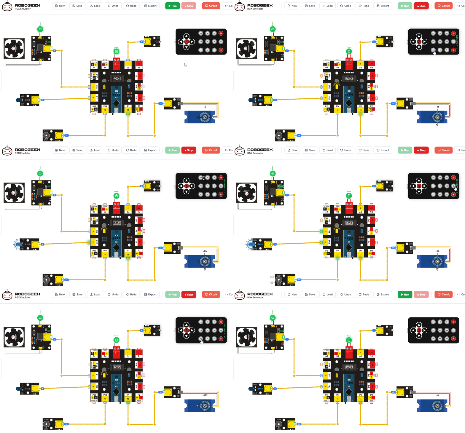
Running the code
Test Your System
1.
Upload your code to the RGX board.
2.
Open Serial Monitor to watch the codes arrive.
3.
Press Button 1: Does the "Window" open?
4.
Press the OK Button: Does the alarm sound? Note: If your hardware doesn't move, double-check that your RJ11 cables are in the correct PINs!
Improve & Extend
•
The "All Off" Button: Can you program a new button to turn the Fan and LED OFF at the same time?
•
Safe Window: Make the Buzzer beep twice whenever Button 1 is pressed so people know the window is moving.
•
Smart Fan: Use an "If" inside a "Case" to make the fan toggle ON and OFF using only Button 4.