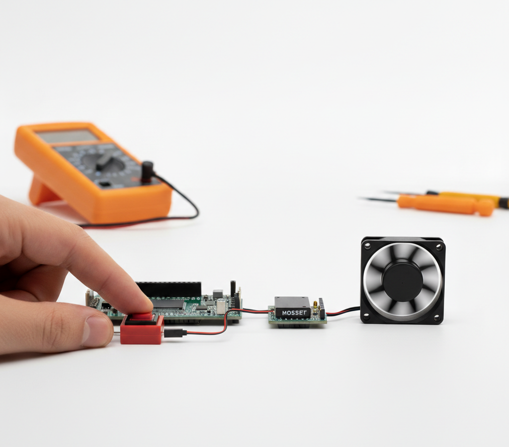
Overview
You will build a DC fan control system using a switch and the RGX Kit.
•
When the switch is turned ON, the DC fan starts spinning.
•
When the switch is turned OFF, the fan stops.
This project is inspired by real-life electric fans and ventilation systems used in homes, offices, and electronic devices.
Objectives
•
How a switch works as a digital input
•
How to control a DC motor (fan)
•
How input devices control output devices in a smart system
Meet the Components
You will use:
•
Switch Module
•
DC Fan (Motor Module)
•
RGX Control Board
•
RJ11 Easy-Plug Cables
Hardware Connections
Component | PIN Connection |
Switch Module | Digital PIN 8 |
DC Fan | PIN 7 |
Make sure all connections are secure using RJ11 cables.
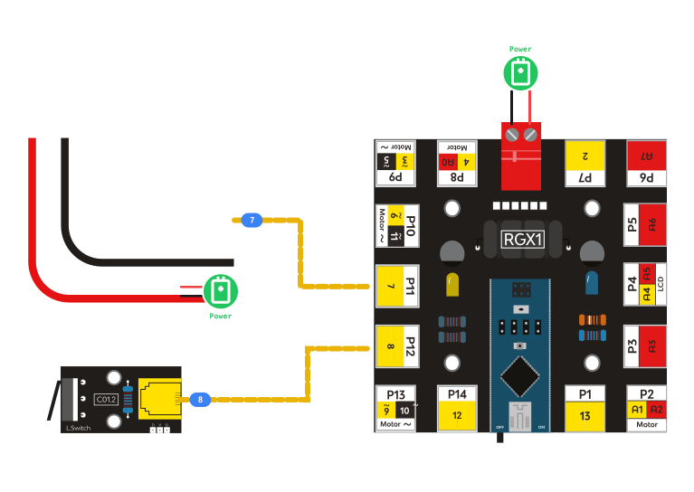
RGX connection
System Signal Flow
The signal moves through the system in this order:
Switch → RGX Board → DC Fan
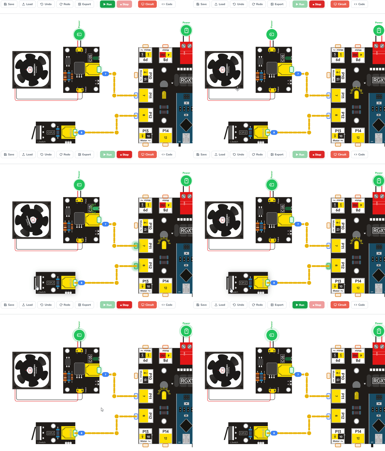
FAN controlled
1.
The switch sends a digital signal.
2.
The RGX board reads the signal.
3.
The board decides whether the fan should turn ON or OFF.
Coding the System
Step 1: Read the Switch
You read the switch connected to PIN 8.
•
1 → Switch is ON
•
0 → Switch is OFF
Step 2: Understanding IF–ELSE
Sometimes a program needs to make a decision.
For example:
•
If the switch is ON → the fan should run.
•
If the switch is OFF → the fan should stop.
To make this decision, we use the IF–ELSE structure.
It works like a question:
IF something is true → do one action
ELSE → do another action
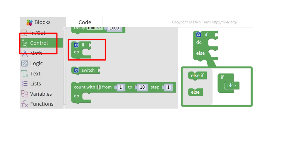
IF-Else block
Step 3: Control the Fan
Understanding the MOSFET Switch
The DC fan is controlled through a MOSFET switch module.
A MOSFET works like an electronic switch that allows the RGX board to control devices that need more power, such as motors or fans.
The RGX board sends a HIGH or LOW signal to PIN 7, which controls the MOSFET:
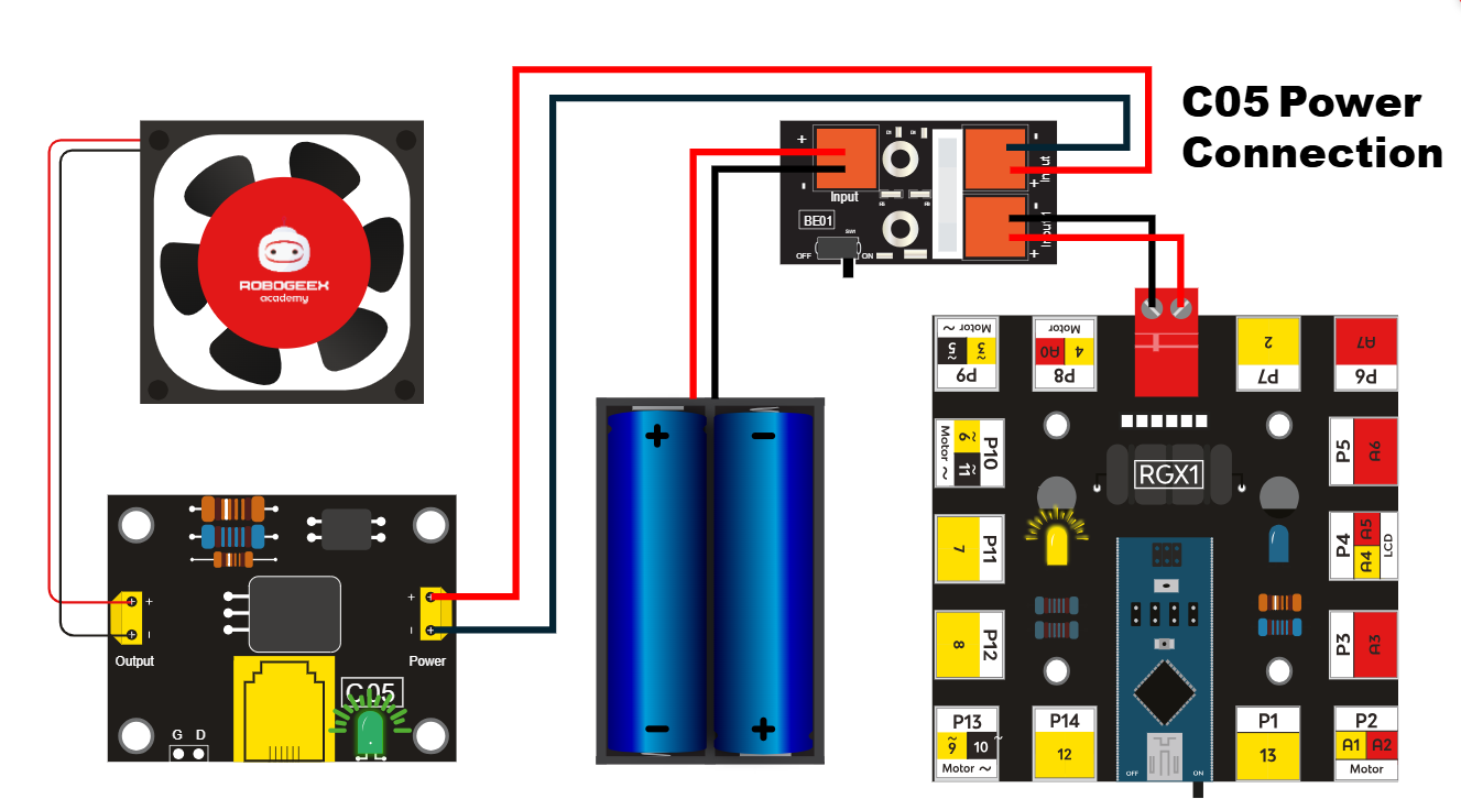
MOSFET switch connecting
Red wire means (+) / Vcc
Black wire means (-) / GND
NOTE
The MOSFET module has two main sides:
Control Side (connected to the RGX board)
Signal (D) → connected to PIN 7
This side receives the control signal from the RGX board.
Power Side (connected to the fan and battery)
Power Input (+ / −) → connected to the battery pack
Output (+ / −) → connected to the DC fan
This side provides the power needed to run the fan.
The MOSFET module has two main sides:
Control Side (connected to the RGX board)
Signal (D) → connected to PIN 7
This side receives the control signal from the RGX board.
Power Side (connected to the fan and battery)
Power Input (+ / −) → connected to the battery pack
Output (+ / −) → connected to the DC fan
This side provides the power needed to run the fan.
When the signal is HIGH, the MOSFET turns ON and allows power to reach the fan, so the fan spins.
When the signal is LOW, the MOSFET turns OFF, stopping the power to the fan.
This method protects the RGX board while allowing it to control higher-power devices.
Logic:
•
If the switch sends HIGH → turn the fan ON
•
Otherwise → turn the fan OFF
Hint
In the IF condition, we use the Logic block “=” (equal).
This block compares two values to check if they are the same.
In the IF condition, we use the Logic block “=” (equal).
This block compares two values to check if they are the same.
Test Your System
1.
Power the RGX board
2.
Turn the switch ON
3.
Observe: Fan starts spinning
4.
Turn the switch OFF
5.
Confirm: Fan stops
If this happens, your system is working correctly
Improve & Extend
Try upgrading your DC fan system:
•
Add an LED indicator when the fan is ON
•
Add a timer to stop the fan automatically
•
Add a temperature sensor to make it automatic
•
Control fan speed using PWM (advanced)