Overview
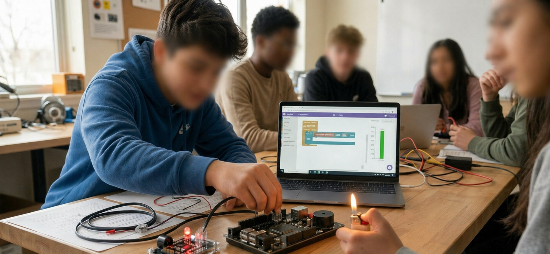
In this lesson, you will build a professional-grade smart fire-detection alarm system using the RGX Kit, similar to safety systems used in homes and industrial environments.
You will explore how a Flame Sensor can work in two ways: as a Digital Input or an Analog Input. This project introduces the concept of environmental monitoring, where the system "measures" the world around it to make critical safety decisions based on intensity.
Objectives
•
How a flame sensor detects fire
•
Understand the technical difference between Digital and Analog signals.
•
Master the 0–1023 numerical scale for analog readings.
•
How sensors and actuators work together in a smart safety system
From Digital to Analog: A New Way to Measure
It is important to understand why we are switching from digital to analog logic for this project.
Recap: Digital Signals (The Button)
In the last project, we used a button. A button is a digital input because it only has two states: HIGH (1) or LOW (0). It is like a standard light switch—it is either pressed or it isn't.

Digital Signals
New Concept: Analog Signals

Analog Signals
Environmental sensors, like the flame sensor, need to tell us more than just "Yes" or "No." They use analog signals to represent a continuous range of values.
•
Nature is analog: fire isn't just "on" or "off"; it can be a tiny spark or a large blaze.
•
While a digital signal is like a switch, an analog signal is like a dimmer knob or a thermometer.
•
The RGX board converts these varying voltage levels into numbers so the computer can understand exactly how intense the fire is.
What does "0 to 1023" mean?
The RGX board uses a 10-bit resolution to read analog inputs. This means it translates the incoming voltage into 1,024 possible steps.
Interpreting the Intensity
Instead of just 0 and 1, we now have a scale from 0 to 1023:
•
0: No signal
•
450: Medium intensity
•
1023: Maximum intensity
By looking at these numbers in the Serial Monitor, you can decide exactly at what "intensity level" your alarm should start ringing.
Meet the Flame Sensor
This is likely your first time seeing this component! The Flame Sensor is a specialized module designed to detect the presence of fire.
Flame Sensor
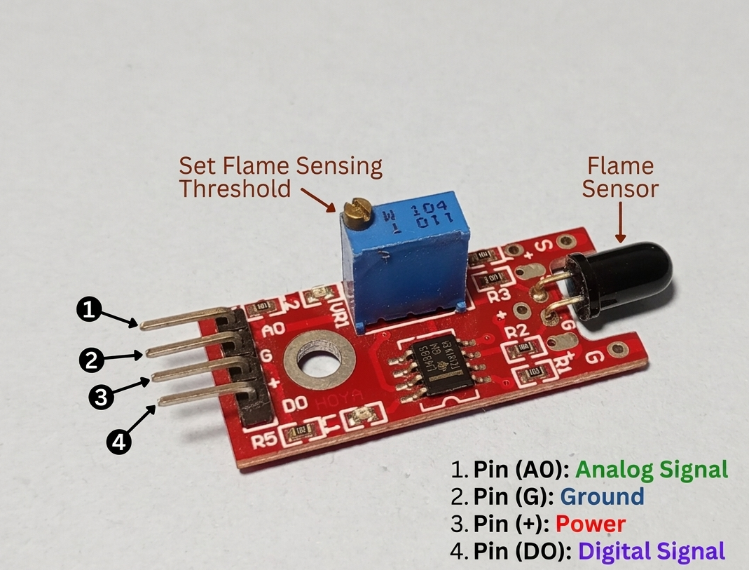
The "Eye": The black bulb at the top is the IR receiver. It picks up infrared radiation which is a type of light invisible to human eyes but very strong in fire. and converts it into an electrical signal for your RGX board.
Sensitivity: It is most sensitive to fire but can also be affected by sunlight or very bright household lamps.
Understanding the Module Pins
Pin (A0) - Analog Signal: This pin sends the intensity range (0-1023). This is the pin we use for smart detection.
Pin (G) - Ground: The negative power connection.
Pin (+) - Power: The positive power connection (usually 5V).
Pin (D0) - Digital Signal: This pin sends a simple ON or OFF. It acts like a switch that triggers when a flame is detected.
The Flame Sensor: Two Modes of Operation
The flame sensor in your kit is versatile because it can act as both a digital and analog device:
1.
Digital Mode (The Switch)
Digital Mode
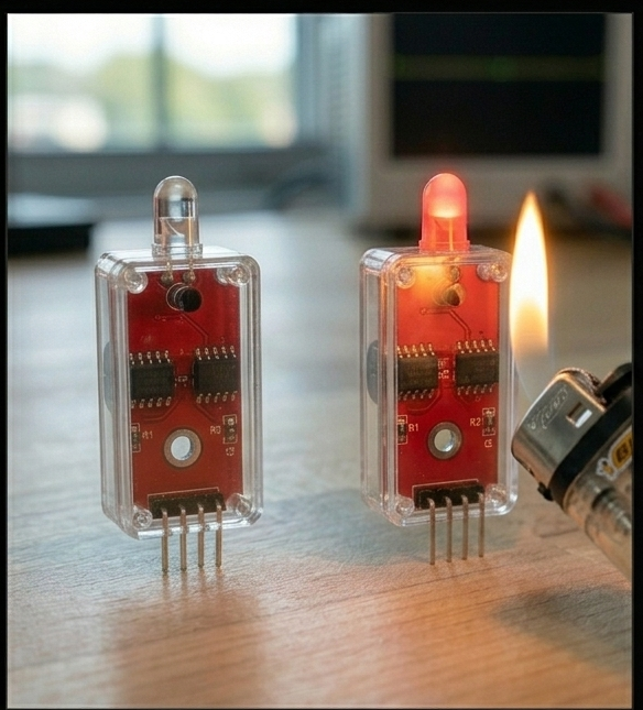
In this mode, the sensor acts like an automatic switch. It internally compares the flame intensity to a limit. If the flame is strong enough, it sends a simple HIGH; otherwise, it sends LOW. You don't see the numbers—just the "Switch" state.
2.
Analog Mode (The Intensity)
Analog Mode
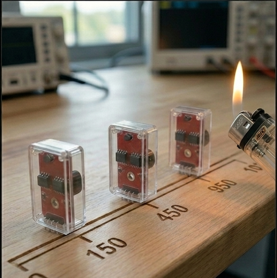
The sensor sends the raw data as a number between 0 and 1023. This allows your code to see the "hidden" levels and decide exactly how to react.
In this lesson, we will focus on Analog mode.
Meet the Components
You will use:
•
Flame Sensor
•
LED Module
•
Buzzer Module
•
RGX Control Board
Hardware & Wiring
Component | PIN Connection |
Flame Sensor | PIN A3 |
LED Module | PIN 7 |
Buzzer | PIN 8 |
Make sure all connections are secure using RJ11 Easy-Plug cables.
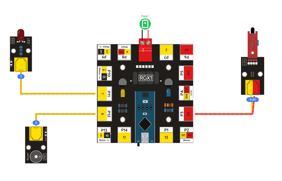
RGX connection
System Logic
In analog mode, the system doesn't just wait for a signal; it constantly asks, "How high is the fire intensity right now?" To make a decision, we use a threshold (a limit).
Condition | LED / Buzzer |
|---|---|
Flame Detected | ON |
Safe | OFF |
This allows the system to react automatically to different levels of fire without any human intervention.
Coding the System
Step 1: Calibration (Finding your Threshold)
Before we program the alarm, we need to see what the sensor "sees" in your room. Run a program to read analog pin A3 and use the Serial Print block.
Fill in the table below based on your serial monitor readings:
Environment Condition | Sensor Value |
|---|---|
Normal Room Light (No fire) | __________ |
Lighter Flame (Near sensor) | __________ |
MY CHOSEN THRESHOLD (Number in between) | __________ |
Step 2: Program the Threshold Logic
Use a Logic (IF/ELSE) block to automate the alarm using your chosen threshold:

coding part
Test Your System
1.
Power the RGX board.
2.
Normal State: The LED should be off and the buzzer quiet.
3.
Trigger: Use a lighter (carefully) near the sensor. Once the value crosses your threshold, the LED will light up and the alarm will sound!
Troubleshooting Note: If the sensor does not seem to react or is always "ON," you may need to adjust the sensitivity. Use a small screwdriver to turn the blue potentiometer (the dial) on the back of the Flame Sensor module until it triggers correctly.
Improve & Extend
Try upgrading your smart fire alarm system:
•
Add a fan to simulate fire suppression
•
Add an LCD to display “Fire Detected!”
•
Add Wi-Fi or Bluetooth for remote alerts
•
Use blinking patterns or delays for warning levels