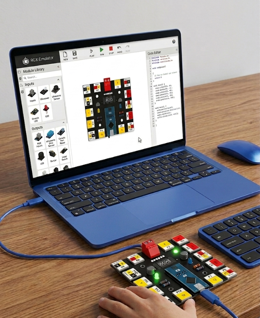
The RGX emulator is a virtual platform where you can build, wire, and code your electronics projects just like you would with a real RGX Kit.
1. Getting Started with the RGX Emulator
To begin your journey, open your web browser and navigate to the official emulator portal:
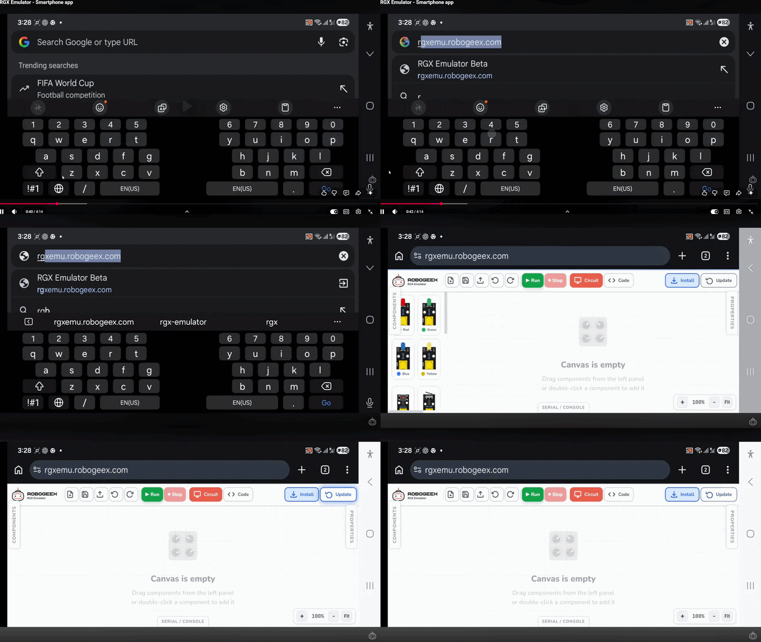
Accessing the Emulator
2. Exploring the Interface
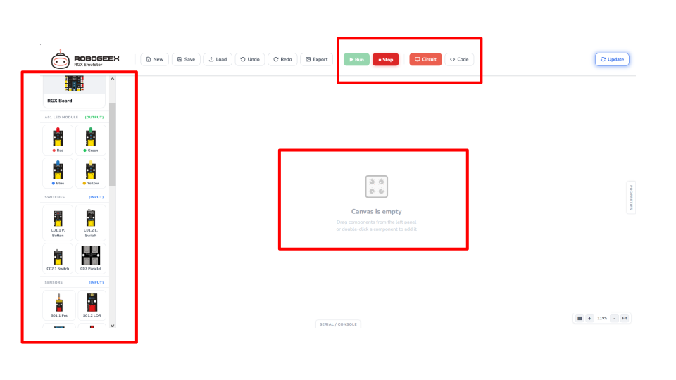
The interface is designed to be intuitive and organized. When you first open the site, you will see a workspace similar to the one below:
There are three main areas you will interact with:
1.
The Canvas: This is the large white central area in the middle. It serves as your "workbench" where you will place and connect components like the RGX Board and LEDs.
2.
The Library: The side menu on the left contains all the modules, such as LEDs (Output) and Switches (Input). You can simply drag and drop them onto the canvas to use them.
the Interface
3.
The Toolbar: Located at the top, featuring buttons to Run your project, Stop the simulation, and toggle between the Circuit view and the Code editor.
4.
The Code Editor: Located on the side, this is the space where you write your code using either visual blocks or text.
3. Building Your First Project
Follow these five simple steps to bring your ideas to life:
•
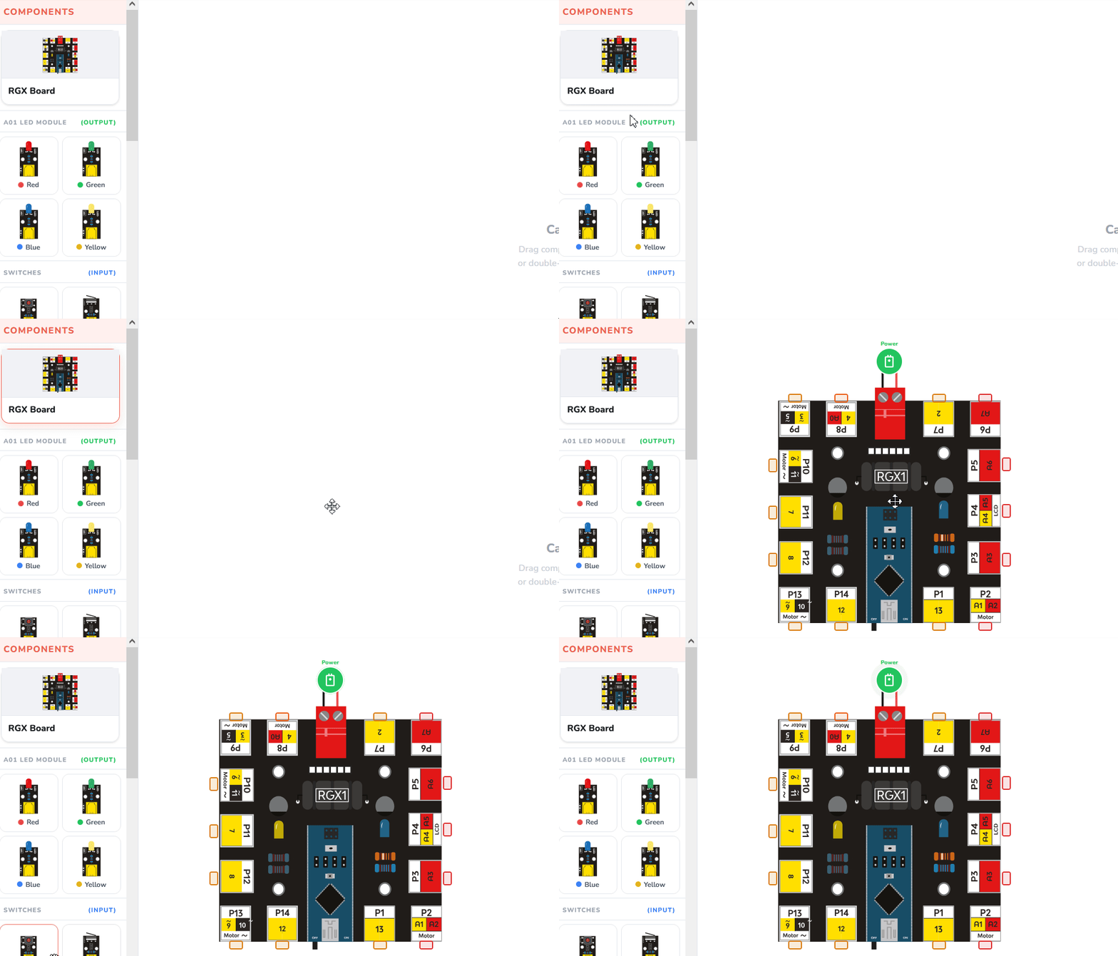
Drag the Board
Start by dragging the RGX Main Board from the top of the library into the center of the canvas. This is the "brain" of your project.
Drag the Board
Add Component
•
Add Components
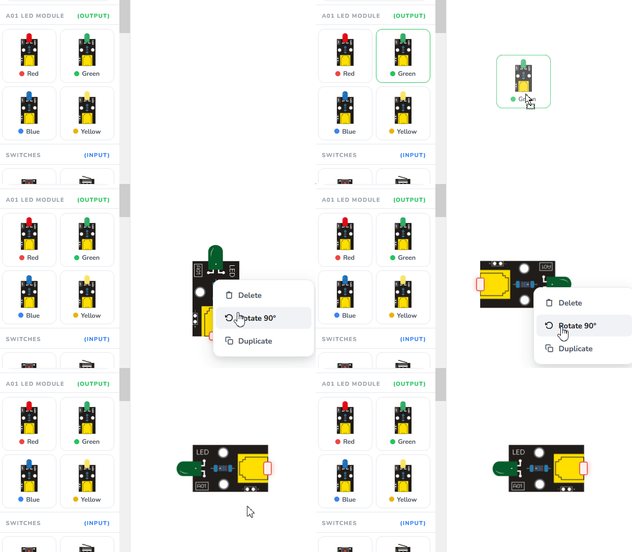
Drag an LED or a Buzzer module from the library.
💡 Pro Tip:
To make wiring easier and keep your project looking clean, you can rotate any component. Simply right-click on the component and click "Rotate 90" to turn it until the ports face the right direction.
To make wiring easier and keep your project looking clean, you can rotate any component. Simply right-click on the component and click "Rotate 90" to turn it until the ports face the right direction.
•
Wiring
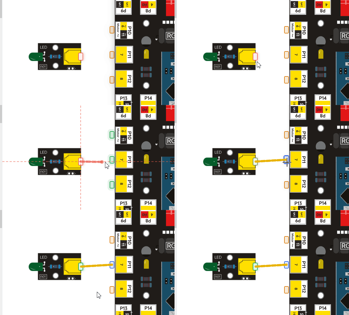
The emulator uses virtual RJ11 cables. Click on a port on your component (like an LED) and drag a wire to a port on the RGX Board .
Wiring
Write Code
•
Write Code
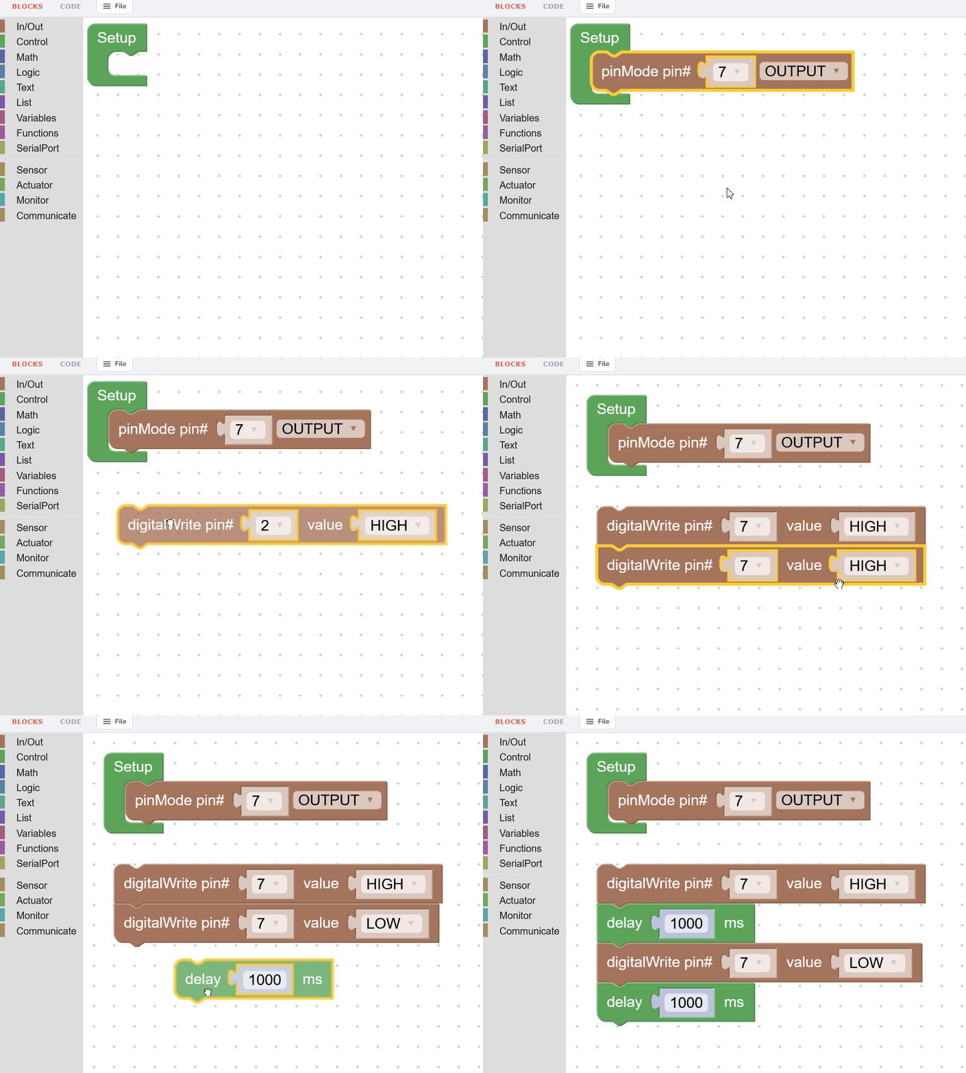
Use the block-based editor to define what happens (e.g., turn on LED").
•
Run Simulation
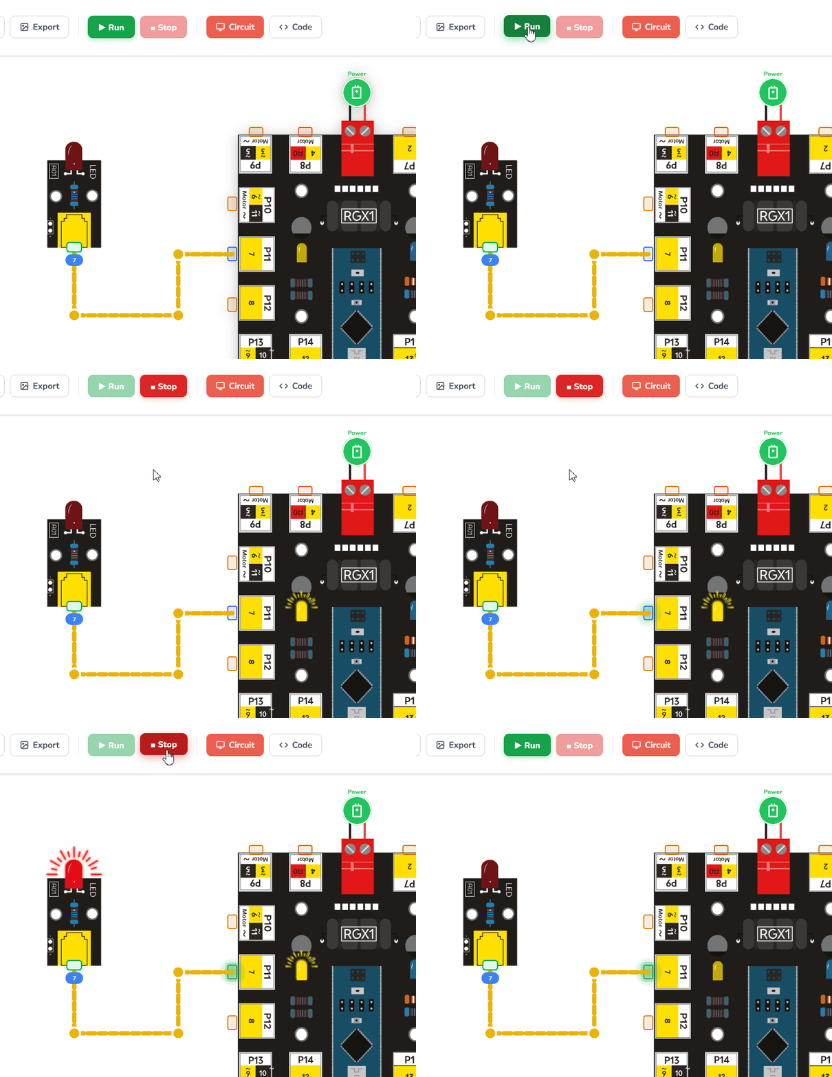
Click the Run button at the top to see your project come to life!
Run Simulation
4. Managing Your Work
According to the platform workflow
Use the top toolbar to manage your progress:
New: Click the New icon to clear the canvas and start a fresh project.
Undo & Redo: Made a mistake? Use the Undo arrow to go back a step, or Redo to restore a change.
Export: Use this to save a high-quality Image of your circuit and connections.
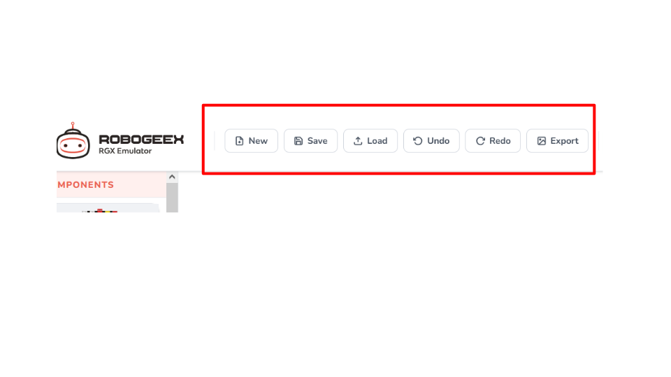
Toolbar
To Save: Click the Save icon in the top menu. This will download a '.mix' or '.ino' project file to your computer , or '.svg' to be an image.
To Load: Use the load icon to browse and upload a previously saved project file back into the emulator.
5. From Virtual to Reality (Uploading)
When you are ready to test your code on a physical RGX board:
1.
Connect: Plug your real RGX Board into your computer using a USB cable.
2.
Verify: In the Code Editor, click the Checkmark (Verify) icon to check for errors.
3.
Upload: Click the Arrow (Upload) icon. Select your device from the browser popup and click Connect. The code will be sent directly to your board!
🎥 Watch the Tutorial: How to Upload boardCode to RGX Board
6. Why Use the Emulator?
No Hardware Needed: Perfect for practicing at home.
Safe Experimenting: You can't "burn" a virtual component!
Easy Collaboration: You can save your project files and send them to your teacher or friends for review.
7. Need More Help?
If you want to explore advanced features, check the port map, or troubleshoot an issue, everything you need is explained in detail in the official documentation: