
Overview
In this lesson, you will build a Sound Sensor System that acts like a real smart home switch. Instead of the light only staying on while it's noisy, your code will "toggle" the light—meaning one clap turns it ON, and it stays on until it hears another sound to turn it OFF.
Objectives
•
Use Variables to store the state of your system.
•
Understand Toggle Logic (switching between two states).
•
Learn to read Digital Input Signals to trigger an event.
New Component : The Sound Sensor
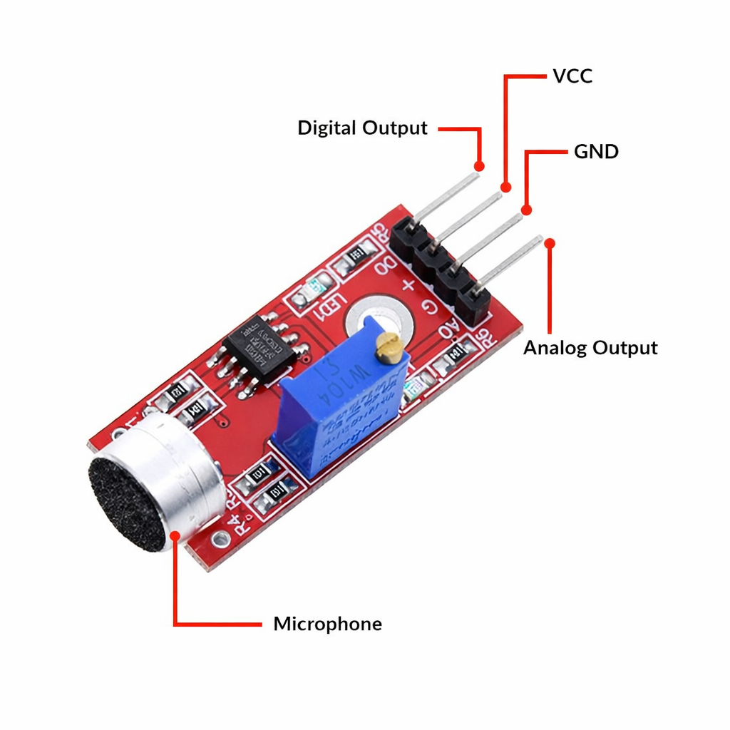
Sound Sensor
The sound sensor acts like a "Digital Ear" for your project.
•
How it works: It uses a tiny microphone to pick up sound waves. When the sound level passes a certain limit, it sends a HIGH signal to your board.
•
Calibration: There is a small blue part called a Potentiometer (the dial).
- Turn Left: Makes it less sensitive (good for loud rooms).
- Turn Right: Makes it more sensitive (detects whispers).
•
Indicators: Most modules have two LEDs. One shows it has power, and the other flashes only when it "hears" a sound.
The sound sensor can actually function in two ways:
Analog Mode: To read the exact "loudness" or intensity of sound (using the AO pin).
Digital Mode: To detect if a sound has simply crossed a certain volume threshold (High/Low).
Analog Mode: To read the exact "loudness" or intensity of sound (using the AO pin).
Digital Mode: To detect if a sound has simply crossed a certain volume threshold (High/Low).
Meet the Components
You will use:
•
Sound Sensor Module
•
LED Module
•
RGX Control Board
•
RJ11 Easy-Plug Cables
Hardware Connections
Component | PIN Connection |
Sound Sensor | Digital PIN 4 |
LED Module | PIN 8 |
Make sure all connections are secure using RJ11 cables.
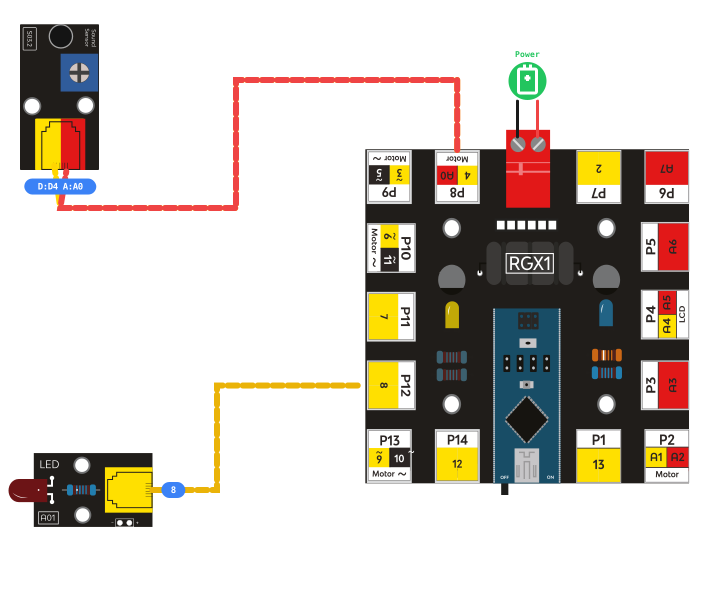
RGX connection
System Logic (The "Toggle" Method)
Your code uses a variable called LEDStatus to remember if the light is currently on or off.
1.
Listen: The system constantly reads the sound sensor on PIN 4.
2.
Detect: If SensorData becomes HIGH (sound detected):
- Check Status: Is the light currently LOW (Off)?
- Yes: Change Memory to HIGH (On).
- No: Change Memory to LOW (Off).
3.
Action: Send the LEDStatus value to PIN 8 to update the light.
Coding the System
Follow the structure shown in your blocks to build the logic:
Step 1: Setup Variables
LED: Set to 8.
Sound: Set to 4.
SensorData: Set to 0 (Stores the live reading).
LEDStatus: Set to LOW (Stores the "Memory" of the light).

Setup Variables
Step 2: Read the Sensor

Read the Sensor
Use digitalRead pin# [Sound] and store the result in the SensorData variable.
Step 3: Nested IF Logic
First IF: Check if SensorData is HIGH.
•
Second IF (Inside the first): Check if LEDStatus is LOW.
- If True: Set LEDStatus to HIGH and digitalWrite the LED.
- Else: Set LEDStatus to LOW and digitalWrite the LED.
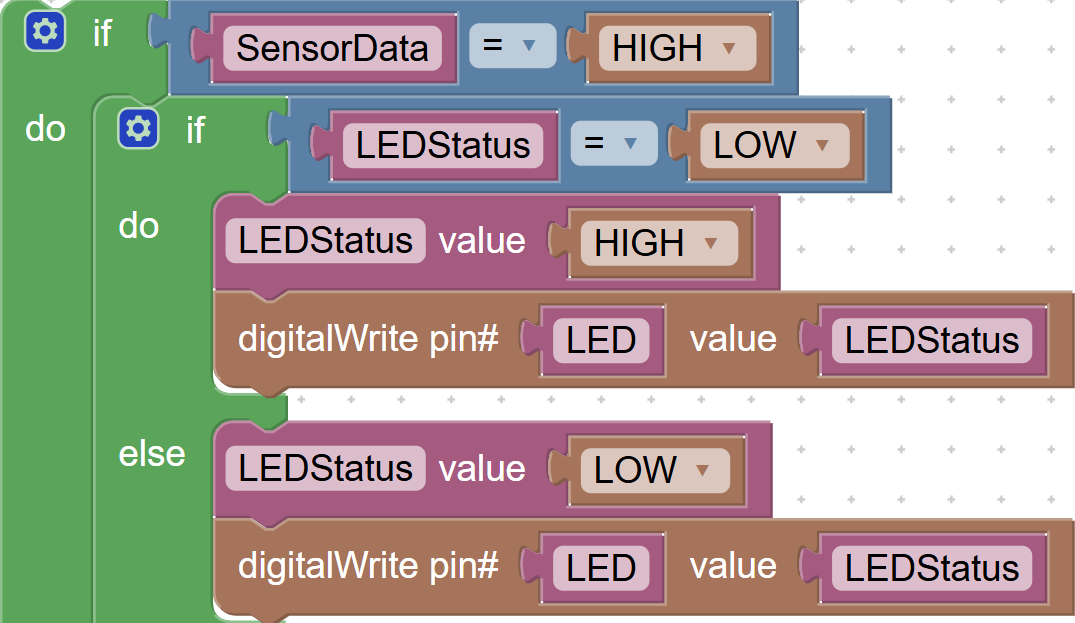
Nested IF Logic
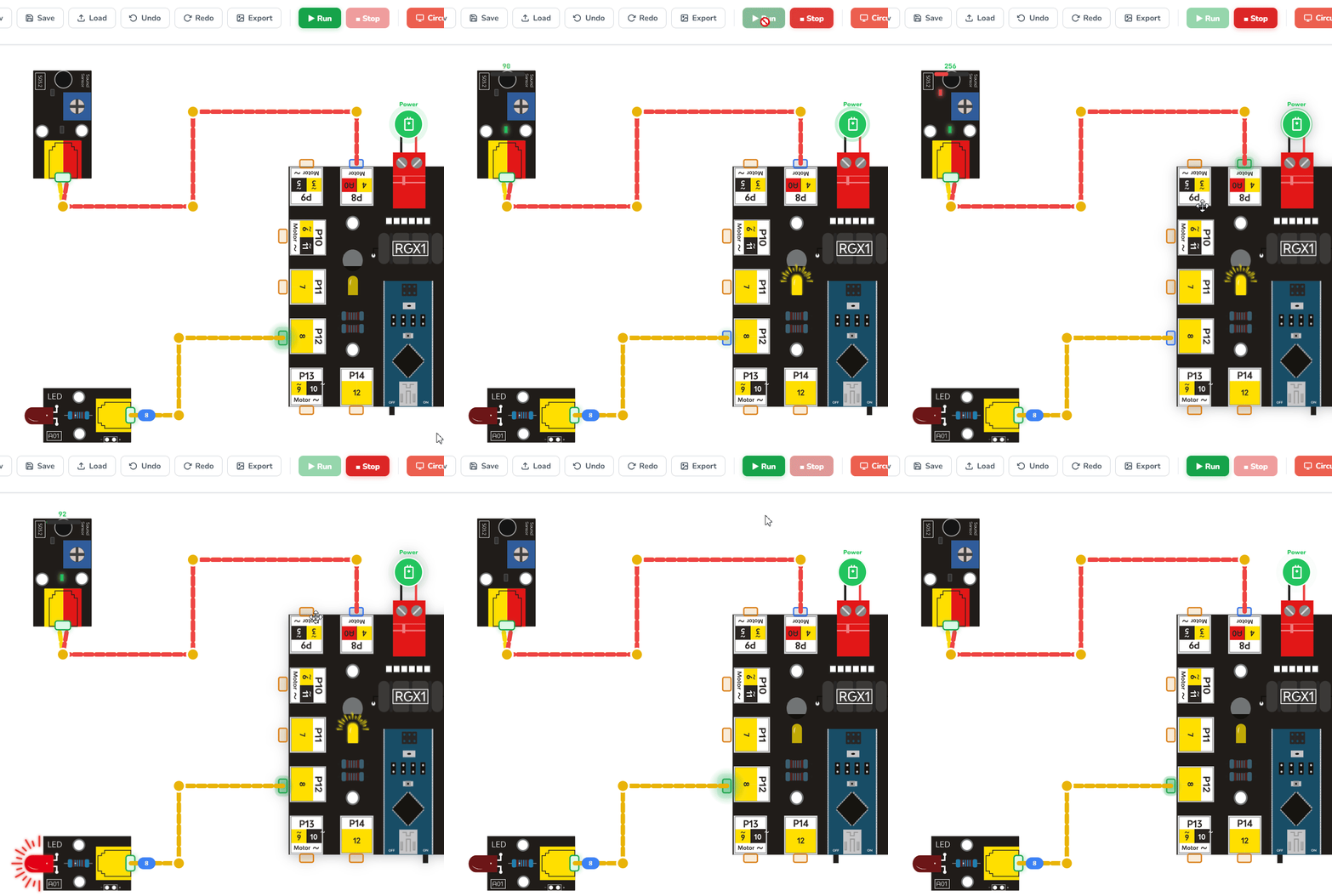
Running the code
Test Your System
1.
Calibration: Clap your hands. If the sensor LED doesn't flash, turn the blue dial until it does.
2.
The First Clap: Give a loud clap. The LED should turn ON and stay on.
3.
The Second Clap: Give another clap. The LED should turn OFF.
If this happens, your Sound Sensor System works correctly
Improve & Extend
•
Anti-Bounce: Add a delay (500ms) at the end of your logic. This prevents the sensor from hearing the "echo" of your clap and turning the light off immediately.
•
Display Status: Use an LCD to show "Status: ACTIVE" when the light is on.