
Overview
In this lesson, you will build a Smart Light System using an LDR (Light Dependent Resistor) and LEDs. This system automatically detects the brightness of the room and decides whether to turn the lights ON or OFF.
This project is a prototype for real-world technology like:

Energy-Saving Offices
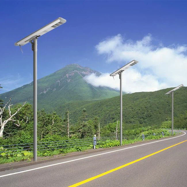
Automatic Street Lights
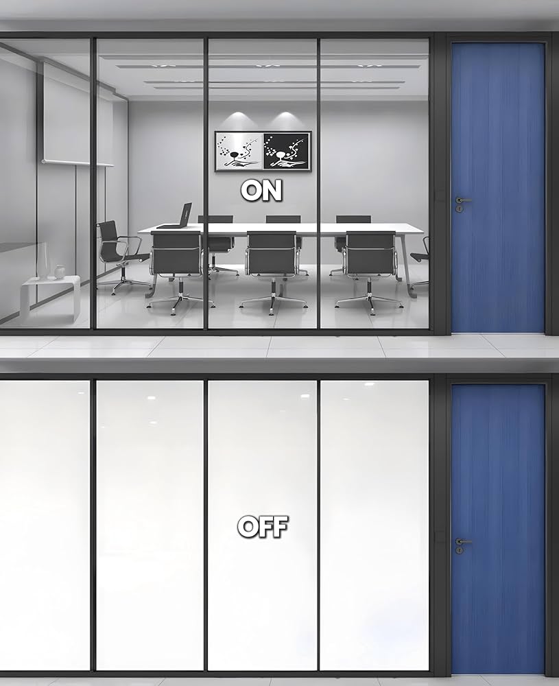
Smart Home Windows
Objectives
•
Understand how an LDR sensor detects light intensity.
•
Learn to read Analog Sensor Values (0-1023).
•
Master the Map Function to simplify complex data.
•
Control multiple LEDs based on environmental conditions.
New Concept:
The LDR (Light-Dependent Resistor)
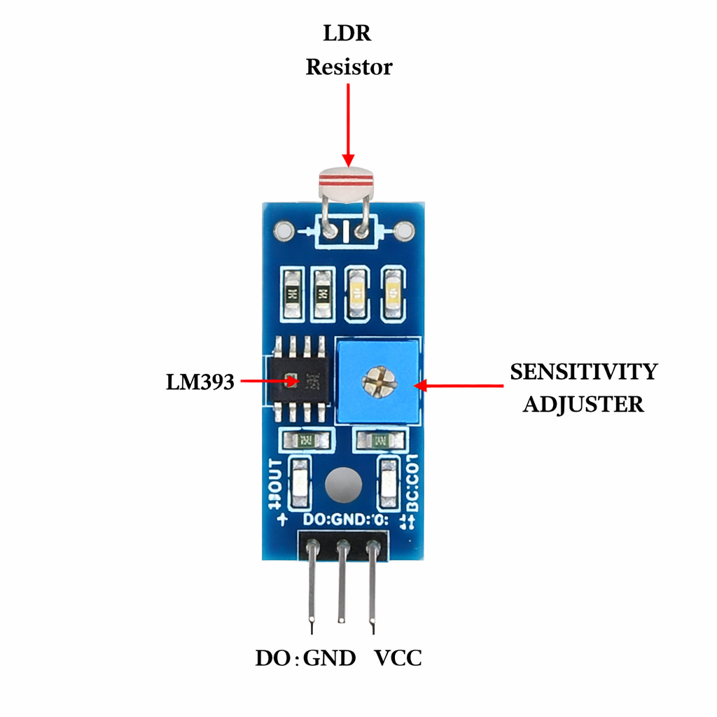
LDR Light Sensor
The LDR is a special type of sensor that "feels" light.
How does it work?
Unlike a button that is either pressed or not, the LDR is an Analog Sensor. It has a special surface made of material that changes its electrical resistance based on the light hitting it.
•
In the Dark: The LDR has very high resistance. It makes it hard for electricity to flow, resulting in a low number in your code (near 0).
•
In the Light: The LDR has very low resistance. It lets electricity flow easily, resulting in a High Number in your code (near 1023).
The "Eyes" of the System
Think of the LDR as the "eyes" of your RGX board. It doesn't see colors or shapes; it only sees Intensity. By measuring this intensity, we can program the board to "wake up" the lights only when the room gets too dark to see.
Meet the Components
You will use:
•
LEDs
•
LDR Light Sensor
•
RGX Control Board
•
RJ11 Easy-Plug Cables
Hardware Connections
Component | PIN Connection |
LDR Sensor | Analog PIN A3 |
LED 1 | PIN 7 |
LED 2 | PIN 8 |
Make sure all connections are secure using RJ11 cables.
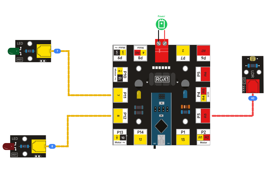
RGX connection
System Logic
The system monitors the raw analog value from the LDR to decide which lights to activate. We use Thresholds (limit numbers) to define "Dark" vs "Bright."
Value | LED 1 | LED 2 |
|---|---|---|
Value < 75 | ON | ON |
Value <175 | ON | OFF |
else | OFF | OFF |
Coding the System
Step 1: Declare Global Variables
We need a storage space to hold the light reading. We need two storage spaces for our data:
1.
ldr (int): To store the raw reading from the sensor (0-1023).
2.
intensity (int): To store the mapped value that we will use for logic.
Step 2: Read and Map
Action: Set ldr to AnalogRead PIN A3.
Mapping helps us simplify the 1024 possible values from the LDR into a smaller range that is easier to manage.

storing data
Step 3: Setting the Light Conditions
Use a series of IF / ELSE IF blocks to manage your energy:
1.
Darkness Detected: IF ldrValue < 75 → Turn ON both Pin 7 and Pin 8 (maximum safety).
2.
Partial Light: ELSE IF ldrValue < 175→ Turn ON Pin 7 and OFF Pin 8 (saving some energy).
3.
Sufficient Light: ELSE → Turn OFF all LEDs. (Maximum energy saving).
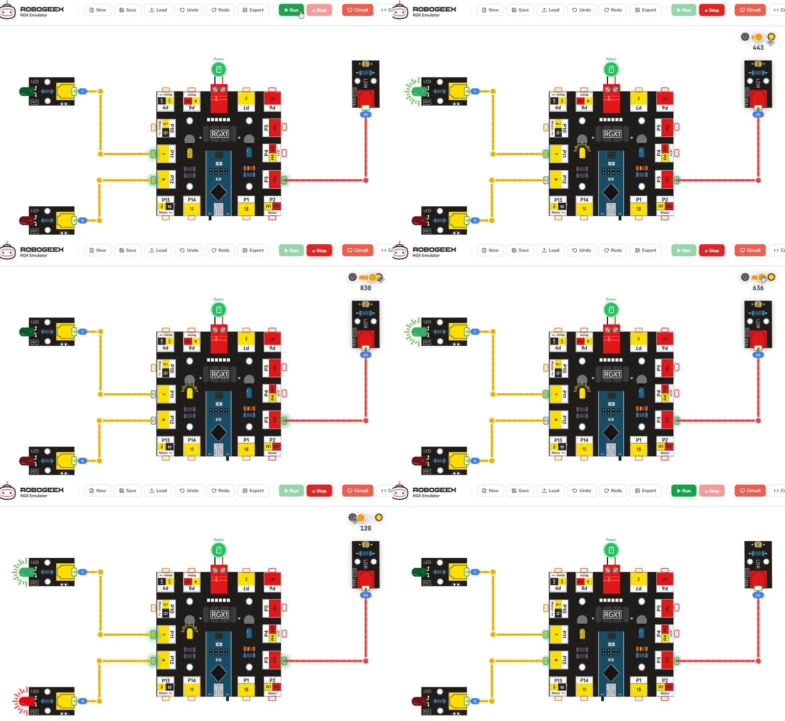
Running the code
Test Your System
1.
Power the RGX board.
2.
Simulation: Use your hand or a piece of cardboard to cover the LDR. The LEDs should turn ON.
3.
Daylight Simulation: Use a flashlight or move the board closer to a window. The LEDs should turn OFF.
4.
Verification: Open the Serial Monitor. Watch how the numbers drop when you cover the sensor and rise when you uncover it.
Improve & Extend
•
Sensitivity Adjustment: Change the numbers (300 and 500) in your code. Can you make the light turn on even if it's only slightly dim?
•
LCD Feedback: Add an LCD to display the message "Night Mode" or "Day Mode" based on the LDR reading.
•
Blinking Warning: Make the LED flash for 3 seconds before it turns off completely to warn people that the lights are shutting down.