Overview
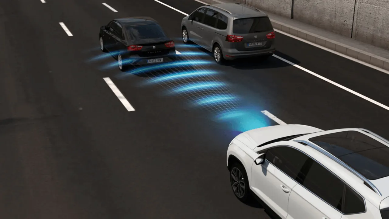
In this lesson, you will build a Smart Accident Prevention System using the RGX Kit. This system acts as an "Emergency Brake Assist" found in modern smart cars.
It uses an ultrasonic sensor to monitor the road ahead of a vehicle model. When an obstacle (like another car or a pedestrian) gets too close:
•
A Warning LED flashes.
•
A buzzer sounds an alert.
•
A servo motor physically activates a brake mechanism.
Objectives
•
Learn how ultrasonic sensors scan for obstacles in real-time.
•
Apply IF / ELSE logic to create a "Safety Zone."
•
Control multiple outputs (LED, Buzzer, and Servo) simultaneously.
•
Understand the mechanics of automatic braking systems.
•
Master the use of Loops (Count Blocks) for repeating alerts.
New Concept: What is a Loop?
Before we start building, we need to understand a fundamental coding concept: The Loop.
What does it mean?
In programming, a Loop is a way to tell a computer to repeat a specific set of instructions over and over again. Instead of writing the same code ten times, you write it once and place it inside a loop.

the loop
Why do we use it?
1.
Efficiency: It makes your code much shorter and easier to read.
2.
Patterns: Loops are perfect for creating patterns, like a blinking light or a pulsing siren.
3.
Automation: It allows the system to keep performing a task (like checking for danger) without stopping.
In this lesson, we will use a specific type of loop called a Count Block to make our emergency alerts repeat, making them much more noticeable to a driver.
Meet the Components
You will use:
•
Ultrasonic Sensor
•
LED Module
•
Buzzer Module
•
Servo Motor
•
RGX Control Board
Hardware Connections
Component | PIN Connection |
|---|---|
Ultrasonic Trig | Echo | PIN 4 | A0 |
LED Module | PIN 7 |
Buzzer Module | PIN 13 |
Servo Motor | PIN 12 |
Use RJ11 Easy-Plug cables to make secure connections.
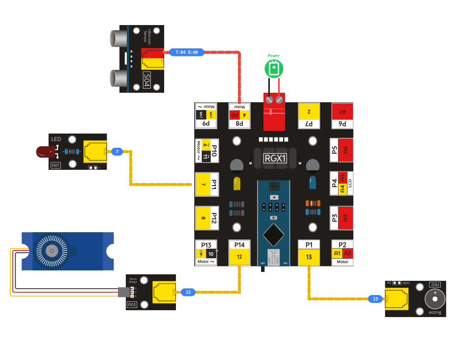
RGX connection
System Logic
The ultrasonic sensor constantly checks the distance in front of the vehicle.
Distance | LED/Buzzer | Servo Brake |
|---|---|---|
Less than 50 cm | ON | Engaged (90°) |
More than 50 cm | OFF | Released (0°) |
If an obstacle gets too close, the system immediately activates warnings and braking.
Automatic reaction helps reduce accidents and improve safety.
Coding the System
Step 1: Declare Global Distance Variable
Condition: Declare global variable Distance as int value 0.
Action:
•
Creates storage for obstacle distance
•
Allows system to constantly monitor the road
•
Update the "Distance" variable constantly.
Step 2: Emergency Mode (The "IF" Trigger) & The Count Block
New Concept: The Count Block (Loops)
When an emergency happens, a single "ON" signal might not be enough to grab a driver's attention. We use a Count Block to create a repeating pattern.
From 0 to 10: Repeats the actions inside 5 times.
By 1: The counter increases by 1 each time.
The "i" variable: Keeps track of which lap the loop is currently on.

count block
Explanation of the Count Block in our system
Let's look at the specific block we are using to create our emergency alert:
1. The Numbers (The Range)
•
From/To: This is the "Starting Line" and the "Finish Line." If you want the LED to flash 10 times, you count from 0 to 10. If you want a shorter warning, you change the "To" value to 5.
•
By (The Step): This determines how the system moves from the start to the end.
- Increase (by 1): Moves forward (1, 2, 3...).
- Decrease (by -1): Moves backward (10, 9, 8...).
Note: Using -1 is very useful for games! You can use it to decrease a player's "Hearts" or "Lives" every time they hit an obstacle.
2. The Counter Variable (i)
•
The "i" variable: This is a temporary container that stores the current "lap number." Every time the loop runs, the value of 'i' changes.
•
Renaming: You can click on
i and rename it to something more descriptive, like 'Blinks' , 'Seconds,' or 'Hearts.' Giving it a name makes your logic easier to explain to others.Action:
1.
Set Servo (Pin 12) to 90°.
2.
Use a Count Block (0 to 10 by 1).
3.
Inside the loop: Turn LED/Buzzer ON, Delay 100ms, Turn LED/Buzzer OFF, Delay 100ms. This creates a rapid flashing alert that ensures the driver sees the danger.
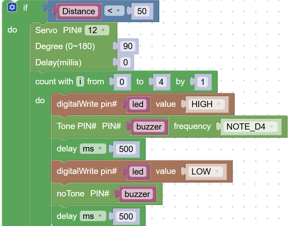
coding blocks
Step 4: Normal Mode ("ELSE" )
Logic: If the road is clear. Action:
1.
Turn OFF the LED and buzzer.
2.
Set Servo to 0°. This releases the brake so the car can move again.
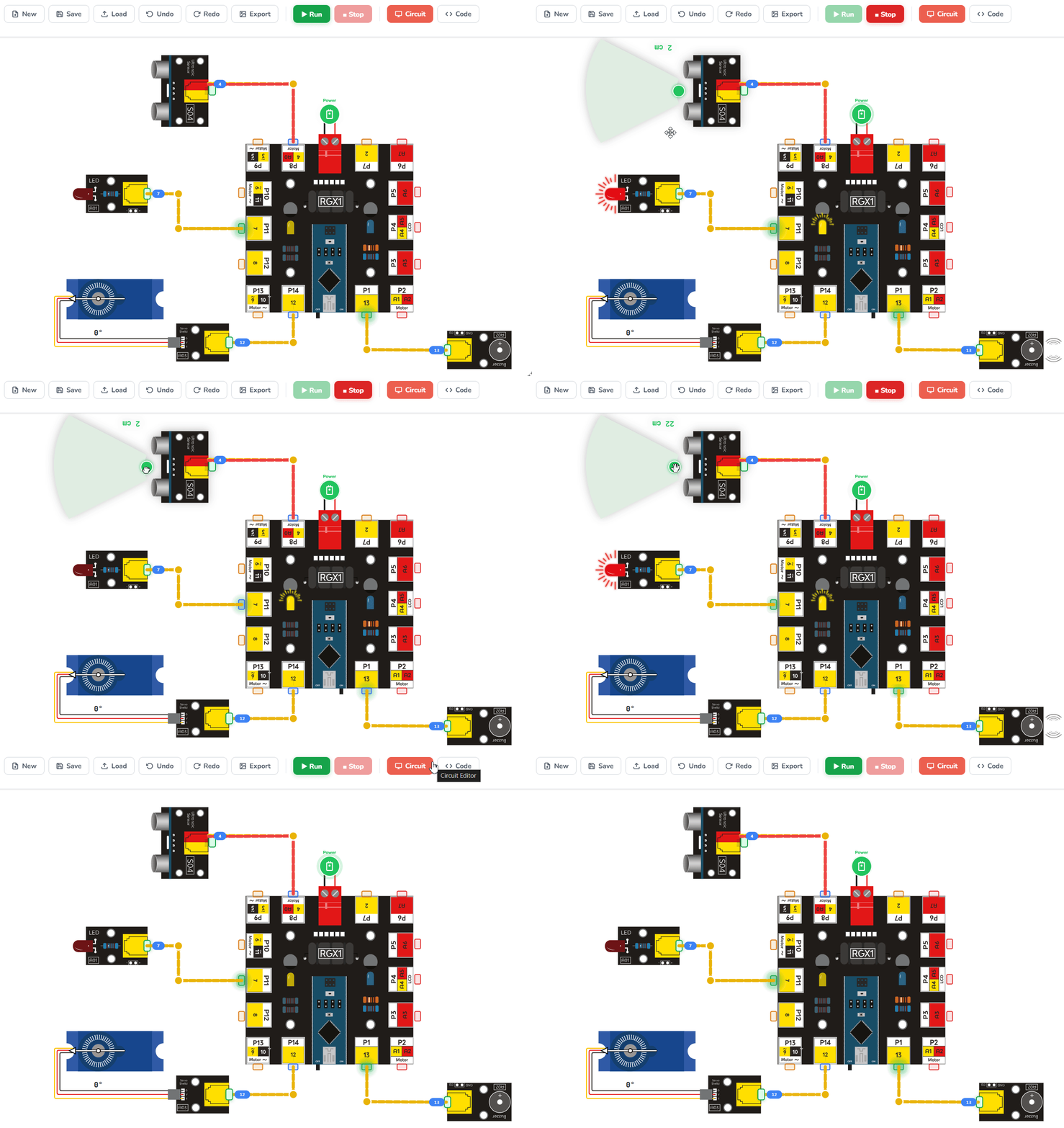
Running the code
Test Your System
Hold an object in front of the sensor:
•
Less than 50 cm → LED + buzzer + brake activated
•
Move object away → System returns to normal
If everything reacts properly, you built a safety system!
Improve & Extend
Try enhancing your system:
•
Add LCD to display messages like “STOP!” or “CLEAR ROAD."
•
Use different buzzer tones for warning levels.
•
Add more sensors to protect from all directions.
•
Control motor speed based on distance