Overview
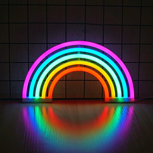
In this lesson, you will build a Smart Rainbow Lamp using the RGX Kit and a Potentiometer. Unlike a simple switch, this system allows you to change lighting patterns smoothly as you rotate a knob.
As the potentiometer value increases, the lamp moves through different "levels" of color and brightness, mimicking modern mood lights and smart ambient systems found in smart homes.
Objectives
•
Understand how a potentiometer works as an adjustable analog sensor.
•
Learn to use 'AnalogRead' to capture precise knob positions.
•
Master complex nested IF / ELSE IF logic for multi-level control.
•
Create interactive lighting patterns based on user input.
NEW COMPONENT: The Potentiometer
Pot
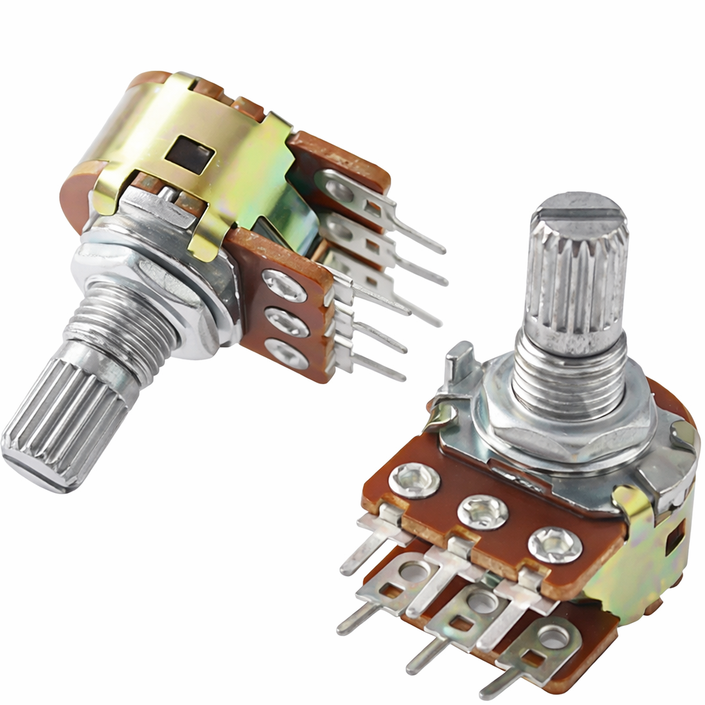
The Potentiometer (often called a "Pot") is a physical knob that you can turn to control the flow of electricity. It is one of the most common ways humans interact with machines!
How it Works: The Physical Dimmer
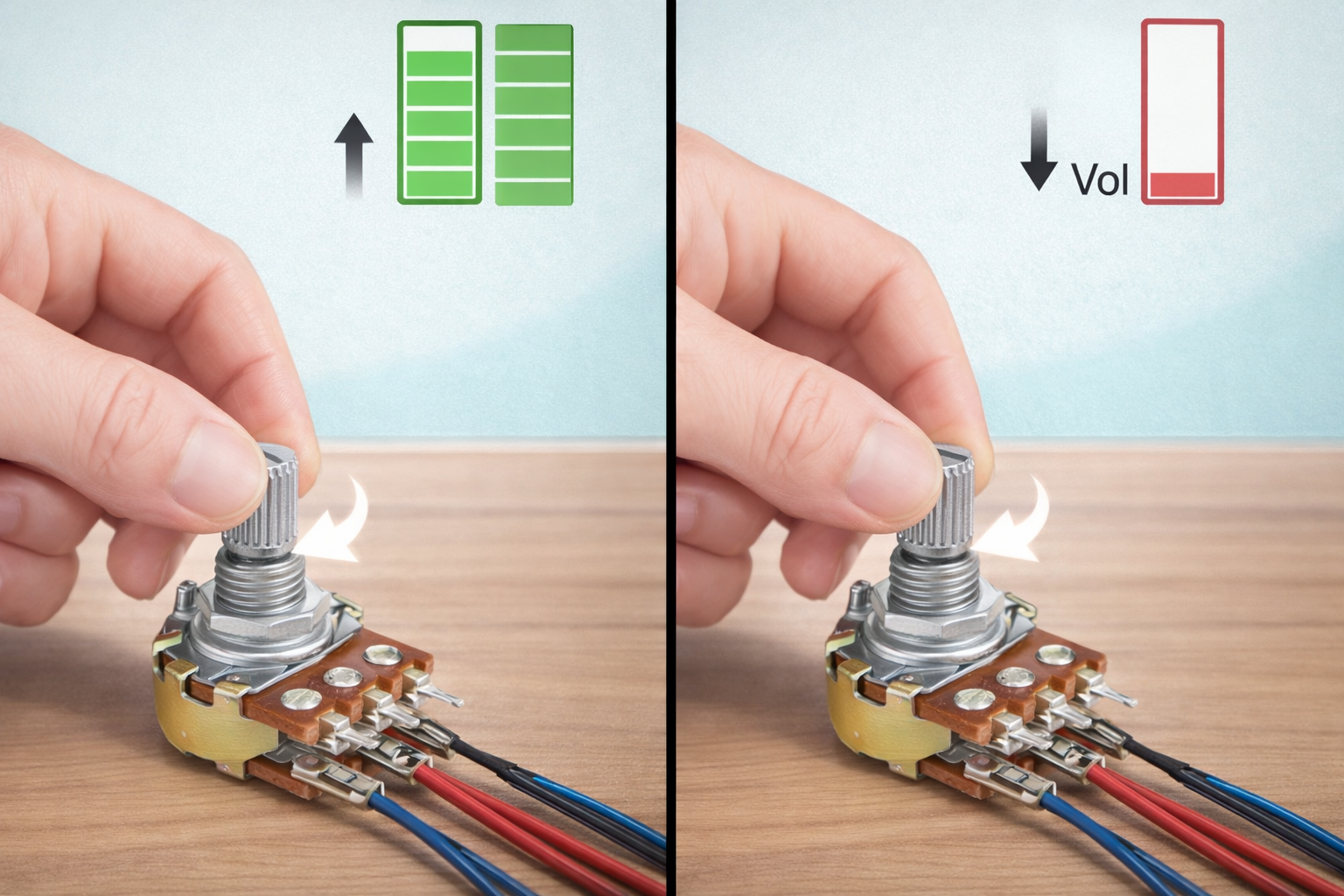
Think of a standard button as a "Light Switch" (it is either ON or OFF). Think of the Potentiometer as a "faucet" or a "Dimmer Knob". As you turn the knob, you are physically changing the resistance inside the component, which allows more or less voltage to pass through to the RGX board.
Understanding the 3 Pins
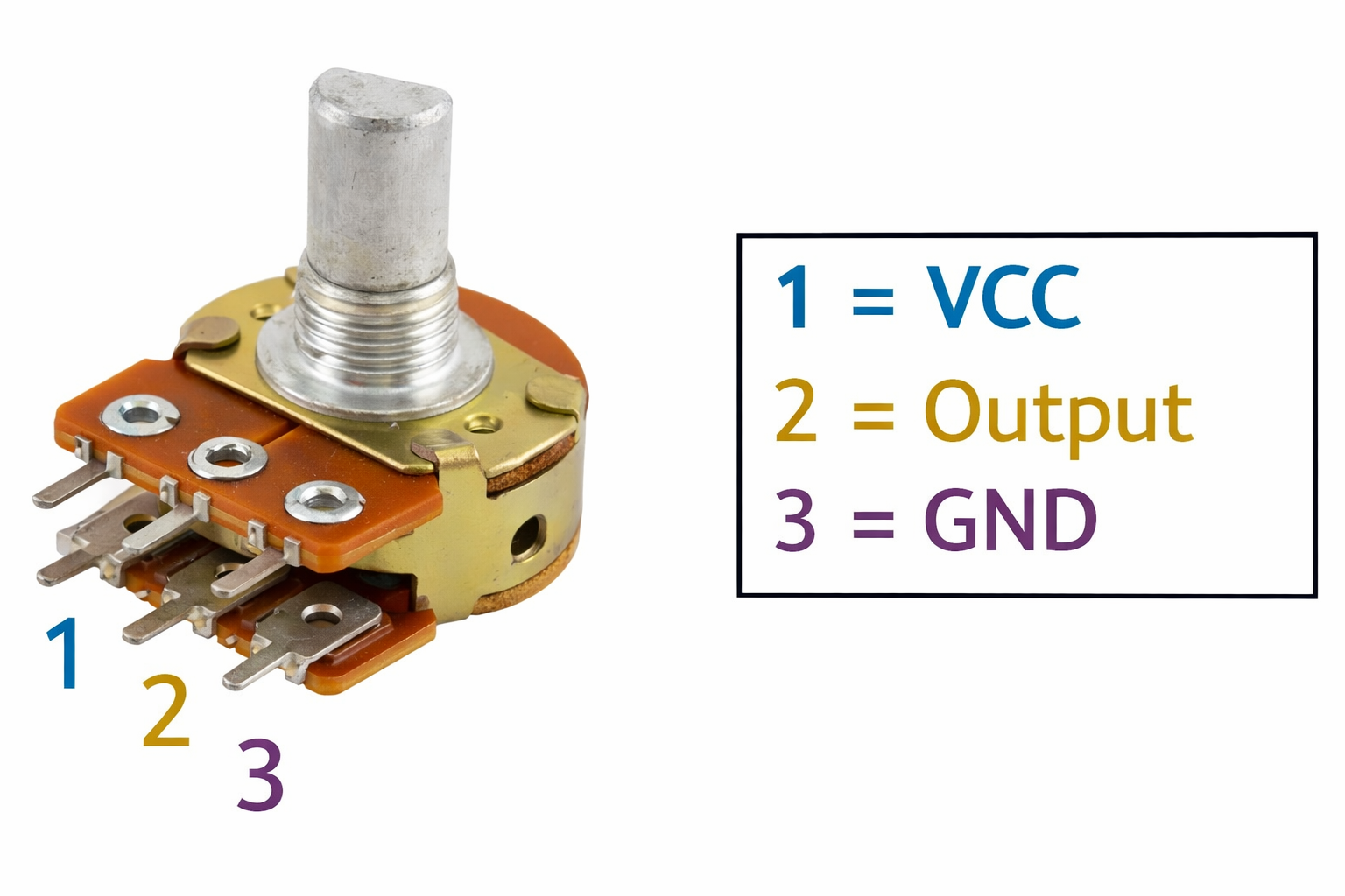
If you look closely at the module, it usually has three internal connections:
pot cnx
1.
VCC (+): Where the power enters.
2.
GND (-): The ground connection.
3.
Signal (Out): The "Output" pin that sends the variable voltage to the RGX board.
The Numerical Language: 0 to 1023
Because the RGX board uses a 10-bit Analog-to-Digital Converter, it translates the physical position of the knob into a number:
•
Fully Left (0): The "faucet" is closed. The board reads
0.•
Middle (512): The "faucet" is halfway open.
•
Fully Right (1023): The "faucet" is wide open. The board reads its maximum value.
Knob
Meet the Components
You will use:
•
Potentiometer Module
•
LED Modules (4 LEDs)
•
RGX Control Board
Hardware Connections
Component | PIN Connection |
Potentiometer | Analog PIN A6 |
LED 1 | PIN 7 |
LED 2 | PIN 8 |
LED 3 | PIN 12 |
LED 4 | PIN 13 |
Make sure all connections are secure using RJ11 cables.
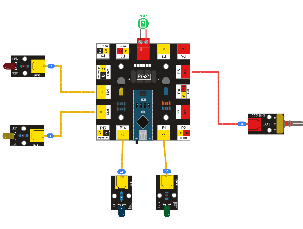
RGX connection
System Logic (The Lighting Levels)
As you rotate the knob, the system checks the value and triggers these patterns to build the rainbow from low to high:
PotValue | LED Pattern | Description |
|---|---|---|
> 800 | Y + G + B + R | Max Level |
> 600 | Y + G + B | High Level |
> 400 | Y + G | Medium Level |
> 200 | Y | Low Level |
Else | All OFF | Standby Mode |
Legend:
•
Y = Yellow LED
•
G = Green LED
•
B = Blue LED
•
R = Red LED
Coding the System
Step 1: Initialize the Variable
Action: Declare a global variable named potmeter (int). This will act as our "memory" to store the knob's position.
Step 2: Read the Knob Position
Action: Use the AnalogRead block for PIN A7. Store this value inside your potmeter variable.
Step 3: Multi-Level Logic (IF / ELSE IF)
We will use a chain of conditions to stack the colors as the value increases:
1.
IF potmeter > 800: Turn ON 7, 8, 12, and 13 (Yellow, Green, Blue, Red).
2.
ELSE IF potmeter > 600: Turn ON 7, 8, 12 and OFF 13.
3.
ELSE IF potmeter > 400: Turn ON 7, 8 and OFF 12, 13.
4.
ELSE IF potmeter > 200: Turn ON 7 and OFF 8, 12, 13.
5.
ELSE: Turn OFF all LEDs.

coding blocks
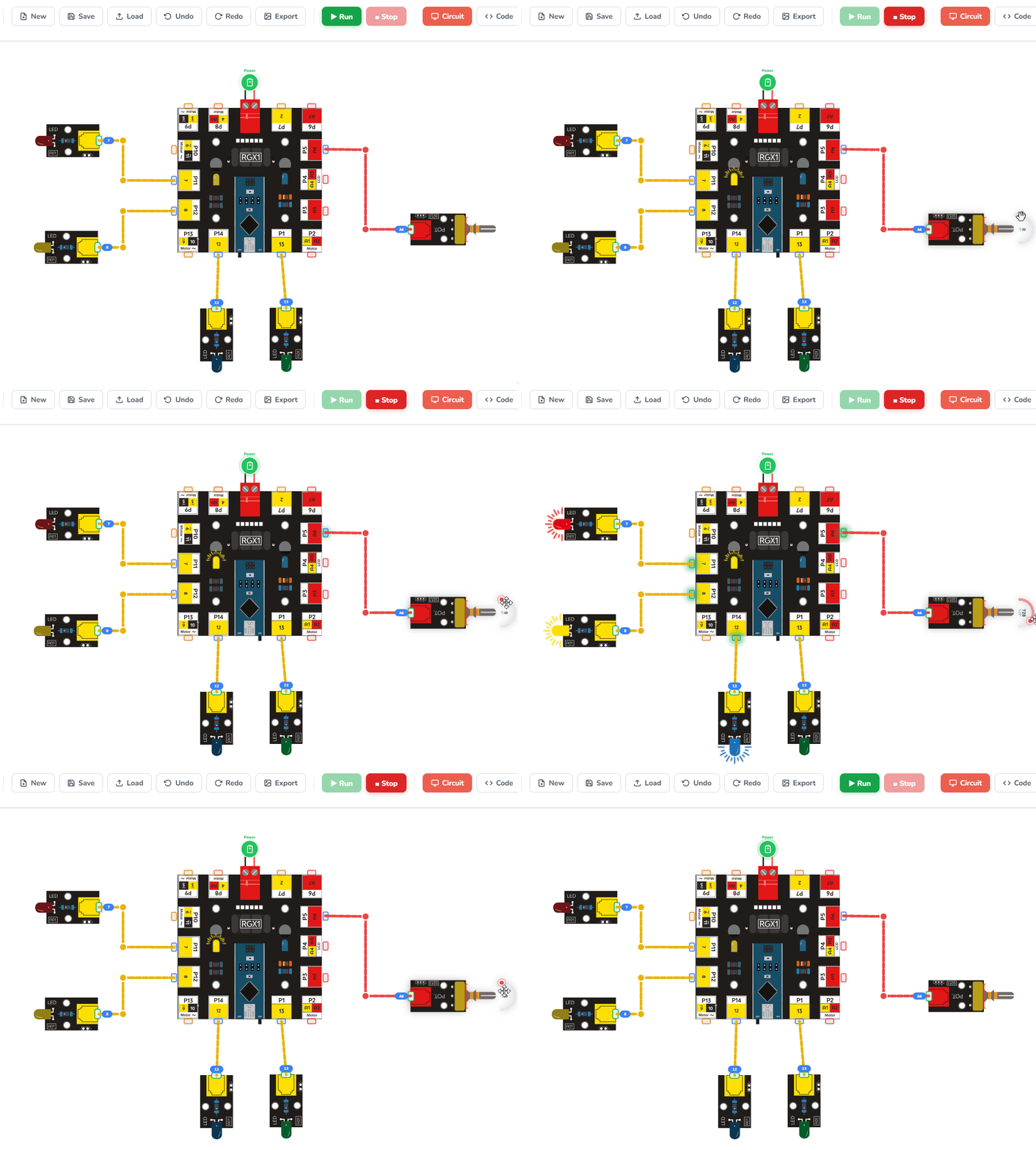
Running the code
Test Your System
1.
Power the RGX board.
2.
Rotate Slowly: Turn the potentiometer knob slowly clockwise.
3.
Observe: Watch the colors appear in order: Yellow → Green → Blue → Red.
4.
Reverse: Turn it back to zero and confirm the colors disappear in reverse.
If this happens, your Smart Rainbow Lamp works correctly
Improve & Extend
•
Fading Effect: Use AnalogWrite (PWM) instead of DigitalWrite to make the LEDs fade in smoothly instead of snapping on.
•
Status Dashboard: Add an LCD to show the exact brightness percentage (0-100%).
•
Sound Reactive: Add a Sound Sensor so the rainbow lamp flashes to the beat of music!