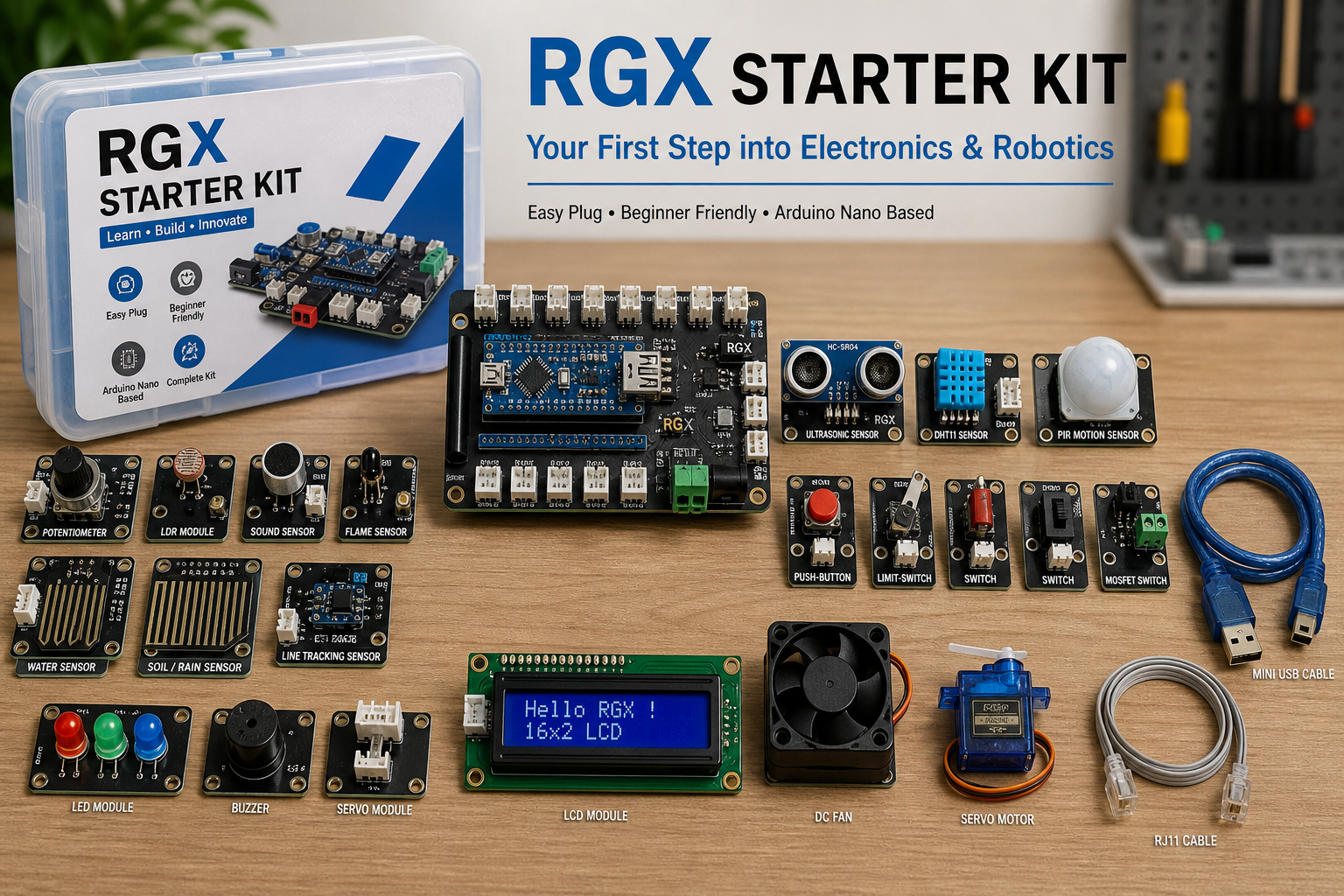
RGX Kit Description
The RGX Starter Kit is a beginner-friendly electronics and robotics kit built around the Arduino Nano, one of the most widely used open-source microcontrollers in education and prototyping. Designed with an Easy Plug interface, the kit allows learners to connect sensors, actuators, and modules without complex wiring, making it ideal for students, hobbyists, and anyone starting their journey in electronics and coding.
The kit is structured to provide a smooth learning experience, even for users with no prior background in programming or circuitry. With its plug-and-play connections, clear labeling, and stable power system, the RGX kit enables users to build functional projects quickly and safely.
RGX Control Board (RGX1)
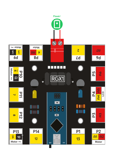
At the core of the kit lies the RGX1 Control Board, an I/O expansion shield designed specifically for the Arduino Nano. It simplifies hardware connections by providing a complete set of labeled Easy Plug ports, organized for intuitive use.
Key Features:
•
8 Digital Ports (P1, P7, P9–P14)
3 of these ports support PWM output for controlling motors, LEDs, or servos.
3 of these ports support PWM output for controlling motors, LEDs, or servos.
•
5 Analog Input Ports (P2–P6)
for reading sensors such as potentiometers, light sensors, and temperature modules.
for reading sensors such as potentiometers, light sensors, and temperature modules.
•
Dual Analog/Digital Interface (P8)
A flexible port is used with modules that can operate in either mode.
A flexible port is used with modules that can operate in either mode.
•
Power Input + USB Port
– USB for programming and power
– DC input for supplying external voltage when needed.
– USB for programming and power
– DC input for supplying external voltage when needed.
•
Built-in Voltage Regulator (5V / 5A)
– Ensures consistent power delivery
– Maintains stable Arduino performance even when multiple modules are connected.
– Ensures consistent power delivery
– Maintains stable Arduino performance even when multiple modules are connected.
Sensors
Potentiometer – S01.1
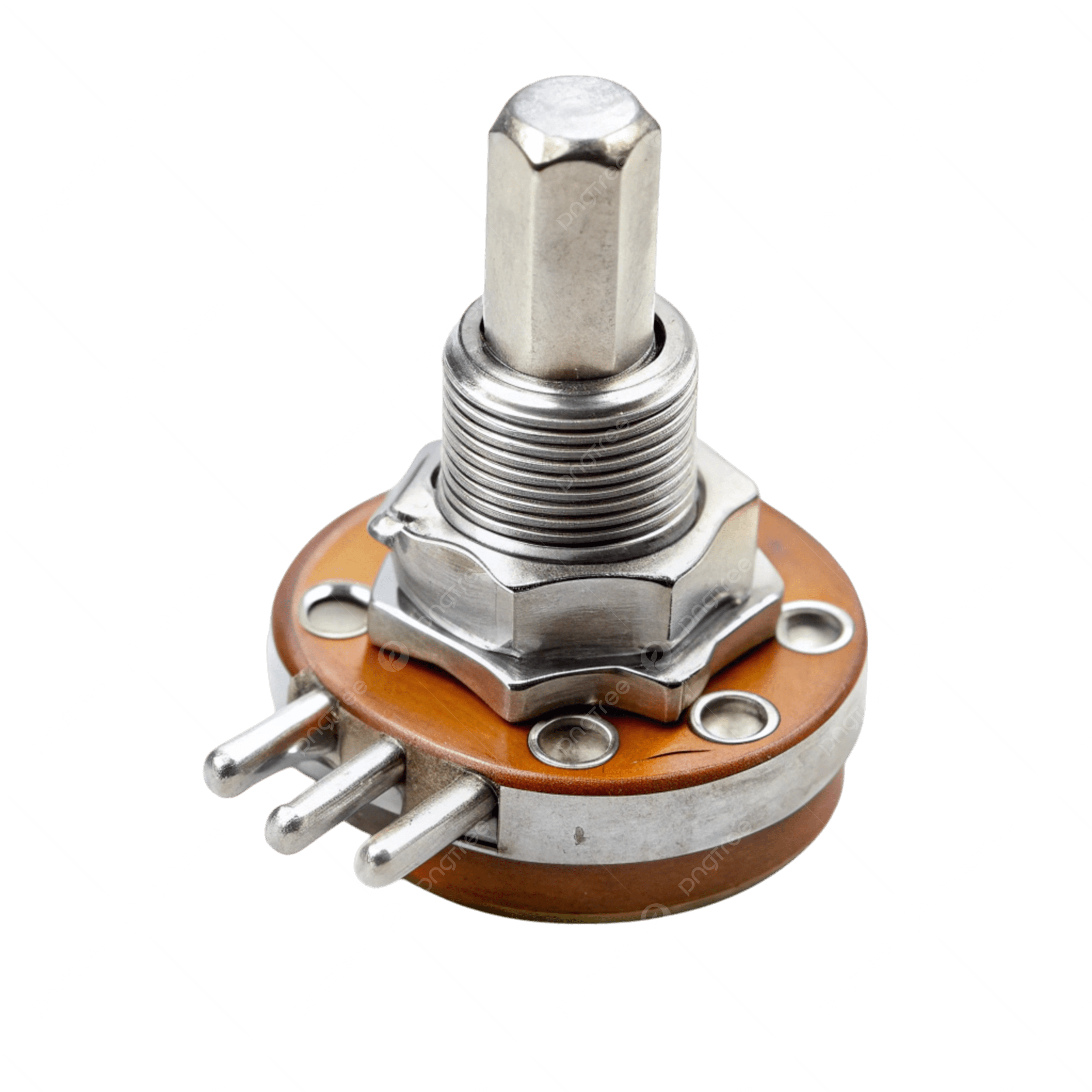
Type: Analog Sensor
Description: A simple rotating device that changes its resistance when the shaft is turned. This change in resistance produces a varying analog voltage that can be read by the RGX control board.
What It Does & Why It Matters:
•
Allows control of values manually (brightness, speed, volume, input level).
•
Useful for adjusting parameters in real-time.
•
Essential for learning analog input reading.
Key Features:
•
Smooth rotational control
•
Produces variable voltage
•
Easy Plug compatibility
How It Works (Behind the Scenes):
The potentiometer is a variable resistor. As the knob turns, the internal wiper moves across a resistive track, changing the output voltage between 0 and 5V. The Arduino reads this voltage as a value from 0 to 1023.
Wiring:
Connect the module to Analog Port P3-P5-P6 on the RGX1 board.

Block-based Mixly program for the potentiometer module
LDR Module – S01.2
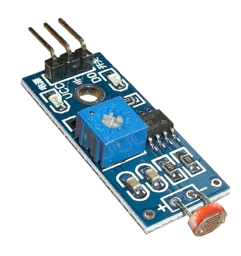
Type: Analog Sensor
Description: A light-dependent resistor (LDR) that changes its resistance based on the surrounding light intensity.
What It Does & Why It Matters:
•
Detects brightness levels
•
Helps create automatic lighting systems
•
Allows students to understand analog-to-digital conversion
Key Features:
•
Sensitive to light changes
•
Simple and reliable
•
Long lifespan
How It Works:
The sensor’s resistance decreases when exposed to higher light intensity and increases in the dark. The RGX board reads these changes as analog values.
Wiring:
Connect to Analog Port P3-P5-P6

Block-based Mixly program for LDR
Ultrasonic Sensor – S04
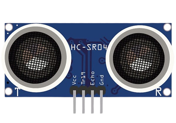
Type: Dual Analog-Digital Sensor
Description: A distance-measuring sensor that emits ultrasonic waves at 40kHz. It calculates the distance by measuring the time for the wave to bounce back after hitting an object.
What It Does & Why It Matters:
•
Measures accurate distance without touching objects
•
Used in robotics for obstacle avoidance
•
Helps understand timing, waves, and sensors
Key Features:
•
Up to several meters range
•
High precision
•
Dual mode compatibility
How It Works:
The module sends a burst of ultrasonic sound waves, waits for the echo, then computes distance using:
distance = (time × speed of sound) / 2
distance = (time × speed of sound) / 2
Wiring:
Use Port P8 (analog-digital dual interface).

Block-based Mixly program for ultrasonic sensor
DHT11 Sensor – S06.1
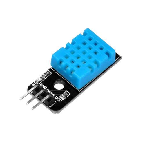
Type: Digital Sensor
Description: A basic sensor that measures temperature and humidity using a capacitive humidity sensor and a thermistor.
What It Does & Why It Matters:
•
Reads real-time humidity % and temperature °C
•
Ideal for weather stations
•
Introduces students to digital sensors and libraries
Key Features:
•
Digital output
•
Stable readings
•
Low power consumption
How It Works:
The sensor internally processes temperature and humidity and then sends the data digitally through a one-wire communication protocol.
Wiring:
Connect to any Digital Port (P1, P7, P11, P12, P14).

Block-based Mixly program for DHT11
Water Sensor – S08
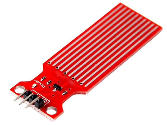
Type: Analog Sensor
Description:
A sensor designed to detect water presence, rainfall, or liquid leakage through measuring conductivity across its plated lines.
What It Does & Why It Matters:
•
Detects water quickly
•
Essential for safety systems
•
Helps learn about conductivity and analog reading
Key Features:
•
Large detection surface
•
Simple interface
•
Fast response time
How It Works:
When water touches the detection plate, conductivity increases, lowering resistance. The sensor outputs higher analog values depending on the amount of water.
Wiring:
Connect to Analog Port P3-P5-P6.

Block-based Mixly program for water sensor
Sound Sensor – S03.2
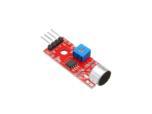
Type: Analog Sensor
Description: A microphone-based module that detects sound levels in the environment and converts them into varying analog signals readable by the RGX board.
What It Does & Why It Matters:
•
Detects claps, noise, and sound patterns
•
Useful in interactive and smart control systems
•
Great for learning about analog threshold detection
Key Features:
•
Built-in microphone
•
Sensitivity adjustment
•
Fast response
How It Works:
The microphone converts sound vibrations into electrical signals. The onboard amplifier scales these signals, producing an analog value representing sound intensity.
Wiring:
Connect to Analog Port P8.

Block-based Mixly program for sound sensor
Flame Sensor – S03.1
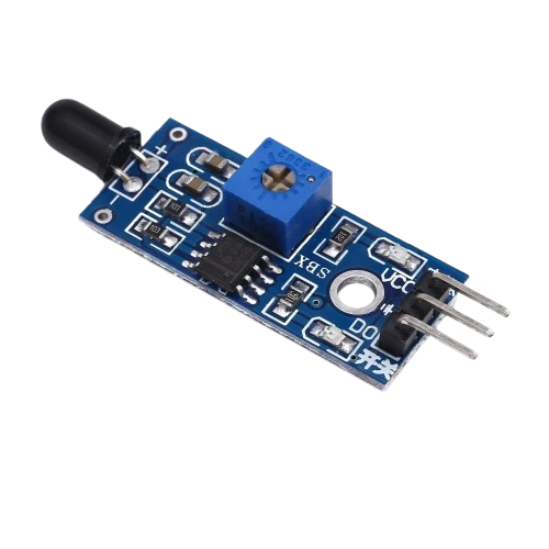
Type: Analog Sensor
Description: A sensor that detects flame or infrared light emitted by fire. It outputs an analog value depending on flame intensity.
What It Does & Why It Matters:
•
Detects flames from a safe distance
•
Ideal for fire alert projects
•
Helps understand infrared detection principles
Key Features:
•
IR-sensitive photodiode
•
Fast flame response
•
Long detection range
How It Works:
The module senses IR radiation (around 760 nm–1100 nm). When fire is present, IR levels increase, lowering sensor resistance and increasing output value.
Wiring:
Connect to Analog Port P8.

Block-based Mixly program for flame sensor
PIR Motion Sensor – S05
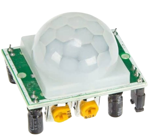
Type: Digital Sensor
Description: A passive infrared sensor that detects human motion based on changes in ambient infrared radiation.
What It Does & Why It Matters:
•
Detects motion without physical contact
•
Common in security systems
•
Teaches students digital input handling
Key Features:
•
Wide detection range
•
Adjustable sensitivity
•
Digital HIGH/LOW output
How It Works:
The sensor contains two IR-sensitive elements. When motion changes the IR distribution, the sensor outputs a digital HIGH signal.
Wiring:
Connect to Digital Port (P1, P7, P1, P12, P14).

Block-based Mixly program for PIR
Line Tracking Sensor – S02
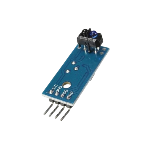
Type: Analog Sensor
Description: An infrared reflective sensor that detects the difference between dark and light surfaces—used mostly in line-following robots.
What It Does & Why It Matters:
•
Detects black lines vs. white backgrounds
•
Essential for robotics navigation
•
Helps understand reflective IR technology
Key Features:
•
Built-in IR LED + photodiode
•
Fast switching output
•
High accuracy on smooth surfaces
How It Works:
The IR LED emits light; white surfaces reflect it while black absorbs it. Reflection difference creates HIGH or LOW digital output.
Wiring:
Connect to Digital Port P8.

Block-based Mixly program for line tracking
Soil / Rain Sensor – S09
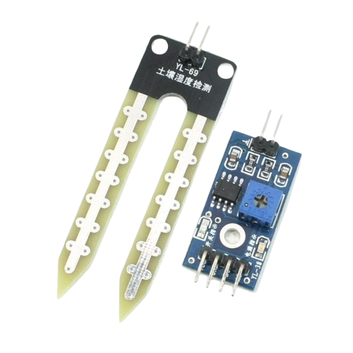
Type: Analog Sensor
Description: A sensor that measures moisture or rainfall by detecting conductivity between its metal traces.
What It Does & Why It Matters:
•
Detects soil moisture for plants
•
Detects rain or water droplets
•
Important for environmental and smart irrigation projects
Key Features:
•
Large detection area
•
Dual-purpose design
•
Analog output based on water presence
How It Works:
Water increases conductivity across the sensor’s traces. The RGX board reads this as a higher analog value.
Wiring:
Connect to Analog Port P3, P5, P6.

Block-based Mixly program for rain sensor
Control
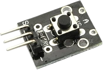
Push-Button – C01.1
Type: Digital Input
Description: A momentary switch used to complete an electric circuit only when pressed. Releases back to its original open state once pressure is removed.
What It Does & Why It Matters:
•
Essential for user interaction (start, stop, reset)
•
Allows students to understand digital inputs and bouncing
•
Simplest way to trigger actions in a system
Key Features:
•
Momentary press
•
Click feedback
•
Easy Plug interface
How It Works
When pressed, the button closes the circuit, sending a HIGH or LOW digital signal to the Arduino depending on wiring and pull-up configuration.
Wiring:
Connect to any Digital Port (P1, P7, P9–P14).

Block-based Mixly program for push button
Limit-Switch – C01.2
Type: Digital Sensor / Switch
Description: A contact-based switch that detects physical movement, presence, or the position of an object when pressed.
What It Does & Why It Matters:
•
Detects object limits or boundaries
•
Common in motors, doors, and robotics
•
Provides safety and position feedback
Key Features:
•
Spring-loaded metal lever
•
Fast actuation
•
High durability
How It Works
The lever arm moves when an object touches it. This closes (or opens) the internal circuit, sending a digital signal to the Arduino.
Wiring:
Connect to Digital Port (P1, P7, P9–P14).
Switch – C02.1
Type:
Digital Control Switch
Description: A basic ON/OFF switch that can be connected to Arduino pins to manually control the digital input state.
What It Does & Why It Matters:
•
Manually sets a digital pin to HIGH or LOW
•
Useful for mode selection and debugging
•
Teaches basics of digital signals and logic states
Key Features:
•
Toggle operation
•
Stable mechanical state
•
Easy to connect
How It Works
The switch physically closes or opens the circuit, outputting a constant state until toggled again.
Wiring:
Connect to Digital Port (P1, P7, P9–P14).
Switch – C02.2
Type: Digital Control Switch
Description: A small sliding switch that toggles between two positions (ON/OFF) and stays in the chosen state until moved manually.
What It Does & Why It Matters:
•
Provides a stable physical state
•
Common for settings and configuration
•
Good for teaching basic digital logic selection
Key Features:
•
Compact slider
•
Two fixed states
•
Simple and reliable
How It Works:
Sliding the switch moves an internal contact between two terminals, setting the signal to HIGH or LOW.
Wiring:
Connect to Digital Port (P1, P7, P9–P14).
MOSFET Switch – C05
Type: Power Control Module
Description: A MOSFET-based module used to control high-current devices such as DC motors, allowing the Arduino to turn them ON or OFF safely.
What It Does & Why It Matters:
•
Controls loads that require more current than the Arduino can supply
•
Protects the microcontroller from damage
•
Enables power management in robotics
Key Features:
•
High-current MOSFET transistor
•
Indicator LED
•
Safe switching of motors and loads
How It Works:
The Arduino sends a digital signal to the gate of the MOSFET.
When the gate receives a HIGH signal → MOSFET conducts → motor or device turns ON.
LOW signal → MOSFET turns OFF.
When the gate receives a HIGH signal → MOSFET conducts → motor or device turns ON.
LOW signal → MOSFET turns OFF.
Wiring:
•
Signal input → Digital Port (P1, P7, P9–P14)
•
Output terminals → Motor or high-current load
•
External power supply when needed
Actuators
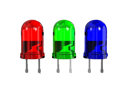
LED Module (A01)
Type: Actuator (Output)
What It Does
The Easy Plug LED Module is a multicolor light output device. It includes three LEDs—Red, Green, and Blue—allowing you to create different lighting effects or indicators.
How It Works
Each color LED is connected to a separate control pin. By sending HIGH/LOW signals (or PWM for brightness control), the module lights up in different single colors or mixed-color combinations.
Where You Use It
•
Status indicators
•
Visual alerts
•
Light effects in projects
•
Color-coded signals
How to Connect
•
Plug the module into the appropriate digital port on the RGX Control Board.
•
Control each LED color using digitalWrite or analogWrite (PWM).
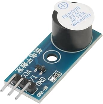
Buzzer (A02)
Type: Actuator (Output)
What It Does
The buzzer is a small sound-output device used to create tones, alerts, and beeps in your project.
How It Works
When the microcontroller sends an electrical signal to the buzzer pin, the internal piezo element vibrates and produces sound. Using the tone() function allows control of pitch and duration.
Where You Use It
•
Alarms
•
Notifications
•
Game sound effects
•
Timers
How to Connect
•
Plug the buzzer into a digital port on the RGX board.
•
Use tone(pin, frequency) or digitalWrite(pin, HIGH/LOW) depending on the sound type.
Servo Module (A03)
Type: Actuator (Output)
What It Does
The Servo Module allows direct connection of standard servo motors through a 3-pin compatible interface (VCC, GND, Signal).
How It Works
A servo rotates to a specific angle (0°–180°) based on a PWM control signal. The RGX Control Board sends a specific pulse width to tell the servo how far to rotate.
Monitor
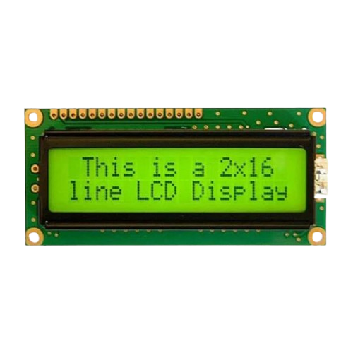
LCD Module (M01)
Type: Monitor (Output Display)
What It Does
The Easy Plug LCD Module is a character display that shows text across 2 rows, with 16 characters per row (16×2). It allows your project to display readings, messages, menus, or system status.
How It Works
The LCD contains an internal controller that receives commands and data from the RGX board. It prints characters using a pixel-based matrix. Using the LCD library, you can send instructions such as cursor movement, printing text, clearing the screen, or adjusting backlight.
Where You Use It
•
Showing sensor readings (temperature, distance, light level…)
•
Displaying system status or warnings
•
Menus and user interfaces
•
Smart systems and interactive projects
How to Connect
•
Connect the module through its Easy Plug port on the RGX Control Board.
•
Use the appropriate LCD library to initialize the screen and print text.
•
Typical functions include: lcd.begin(16, 2)
lcd.print("Hello")
lcd.setCursor(col, row)
lcd.clear()
lcd.print("Hello")
lcd.setCursor(col, row)
lcd.clear()
Motors
DC Fan
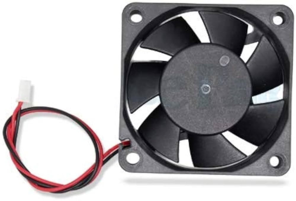
Type: Motor (Actuator)
What It Does
The DC Fan is a small motor with blades used to generate airflow. It can be turned ON or OFF using a motor driver module connected to the RGX board.
How It Works
The fan operates using DC voltage. When the motor driver receives a signal from the RGX board, it supplies power to the fan, causing the blades to rotate. Since the fan only supports simple control, it does not offer speed regulation unless PWM control is added.
Where You Use It
•
Cooling systems
•
Smart ventilation projects
•
Fire detection simulations
•
Airflow or smoke movement experiments
How to Connect
•
Connect the fan to the MOSFET Motor Driver (C05).
•
Connect the driver to one of the digital ports (Easy Plug).
•
Use a digital HIGH/LOW signal to turn it ON or OFF.
Servo Motor
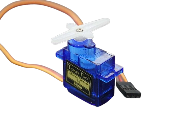
Type: Motor (Actuator)
What It Does
The Servo Motor can rotate its output shaft to a specific angle (usually between 0° and 180°). It is ideal for precise movements.
How It Works
The servo contains a DC motor, gears, and a feedback system. By sending PWM signals from the RGX board, you choose the exact angle you want the shaft to move to. The servo automatically holds its position using internal control circuitry.
Where You Use It
•
Robotic arms
•
Grippers
•
Steering systems (smart cars)
•
Door locks or smart access systems
•
Moving mechanical parts precisely
How to Connect
•
Plug the servo cable into the Servo Module (A03) or directly into the RGX compatible servo port.
•
Use the Servo library, typically: servo.attach(pin);
servo.write(angle);
servo.write(angle);
Cables
Mini USB Cable
Type: Cable (Connectivity)
What It Does
The Mini USB Cable is used to connect the RGX Control Board to the computer. It allows you to upload code, power the board, and enable serial communication.
How It Works
When plugged into the computer, the cable provides both data transfer and 5V power. This allows the Arduino Nano (mounted on the RGX board) to receive programs from the Arduino IDE and communicate through the serial monitor.
Where You Use It
•
Uploading sketches (code)
•
Powering the RGX board during development
•
Serial communication and debugging
How to Connect
•
Connect the Mini USB end to the Arduino Nano’s USB port.
•
Connect the USB-A end to your computer.
RJ11 Cable
Type: Cable (Module Connection)
What It Does
The RJ11 Cable is the main connection cable used with the RGX Easy Plug system. It links sensors, actuators, and modules to the ports on the RGX Control Board.
How It Works
Each RJ11 cable carries power + ground + signal lines, allowing modules to communicate with the control board. The locking connector ensures stable, safe connections with no loose wires.
Where You Use It
•
Connecting sensors (LDR, ultrasonic, temperature…)
•
Connecting actuators (LED, servo module, buzzer…)
•
Connecting control modules (buttons, switches…)
How to Connect
•
Plug one end of the RJ11 cable into the module.
•
Plug the other end into the matching Easy Plug port on the RGX board (P1–P14).