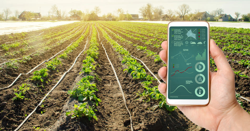
Overview
In this lesson, you will build a Multi-Sensor Smart Farm system. You will use various sensors (LDR, DHT11, and Soil Moisture) to monitor environmental conditions and display them on an LCD. The core focus is learning how to use Function Blocks to manage these multiple sensors. Instead of having one long, confusing program, you will create specific functions for "Soil Moisture," "Temp & Humidity," and "Light Intensity."
Objectives
•
Learn to group sensor-specific logic into organized, reusable blocks.
•
Understand how to read data from LDR, DHT11, and Soil Moisture sensors and display them sequentially.
•
Implement a system where the main loop simply "calls" different environmental monitoring functions.
•
Learn how to convert raw analog data (0-1024) into readable percentages (0-100%).
Meet the components
•
RGX1 Board (with Arduino Nano)
•
LDR Sensor (Light)
•
DHT11 Sensor (Temp/Humidity)
•
Soil Moisture Sensor
•
LED or Buzzer (for alerts)
•
Easy Plug cables
Hardware Connections
Sensor | Pin Connection |
|---|---|
LDR (Light) | Analog Pin A7 |
Soil Moisture | Analog Pin A0 |
DHT11 (Temp/Hum) | Digital Pin 13 |
LED | Digital Pin 7 |
LCD | LCDpin |
Make sure all connections are secure using RJ11 cables.
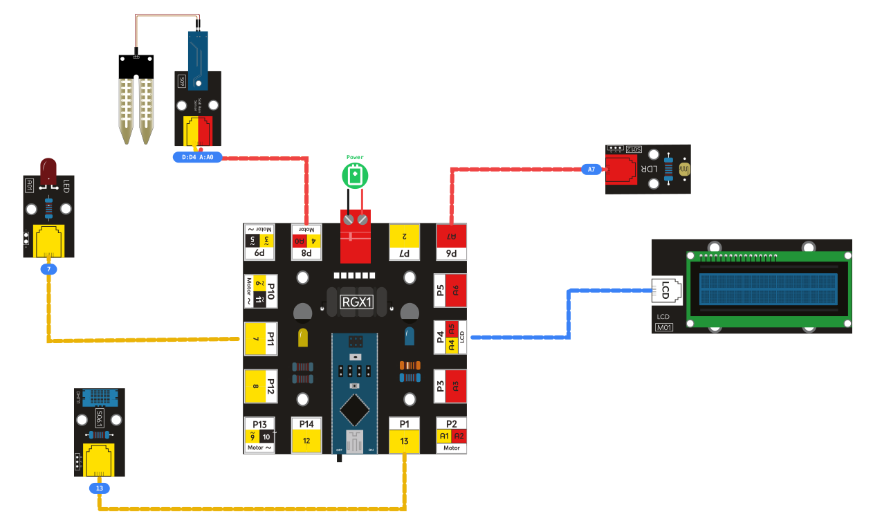
RGX connection
System Logic
The Smart Farm system works by constantly cycling through different environmental checks. Each check is handled by a specialized Function Block.
•
Input: The system reads light levels (A3), soil moisture (A7), and air climate (D7).
•
Processing: Instead of doing everything at once, the board follows a "Carousel" logic—it displays one sensor's data, waits, clears the screen, and moves to the next.
•
Output: The information is translated into human-readable text and percentages on the LCD screen.
Coding the System
The New Concept: Function Blocks
When working with many sensors, your code can become very messy. A Function Block allows you to separate your code into smaller tasks.
•
The Problem: If you put the logic for Light, Soil, and Temp all in the main loop, it becomes hard to fix errors.
•
The Solution: Create a function called Check_Soil. Inside it, put only the soil moisture logic. In your main loop, you just write Call Check_Soil. This makes your code "Modular."
In your code editor, you will see purple blocks labeled "do [name]." These are Function Definitions.
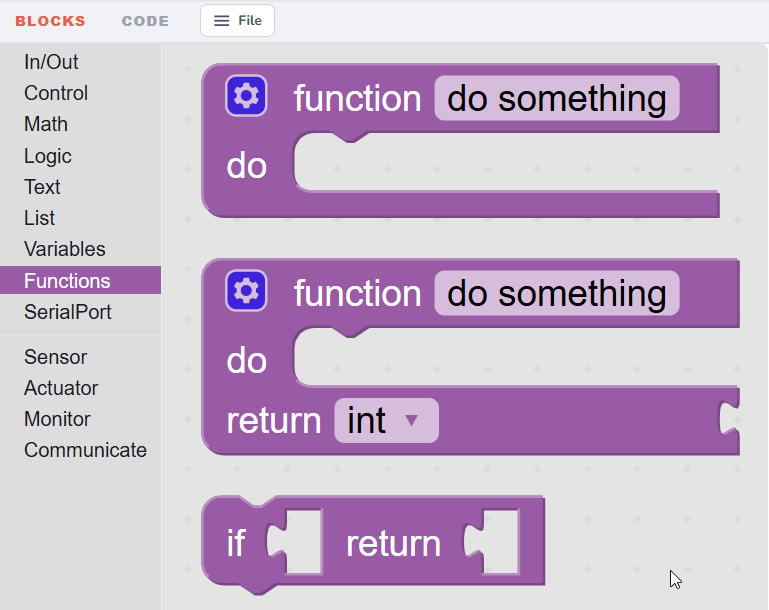
function block
Think of a Function Block like a Recipe:
1.
The Definition : This is where you write the recipe (e.g., "How to check Soil"). The computer stores these instructions but doesn't "cook" them yet.
2.
The Call : This is when you tell the computer "Cook the Soil recipe now!" By placing the small do soil_moisture block inside the Loop, you are triggering the instructions you wrote earlier.
Why use them?
•
Readability: Your main loop stays clean and easy to read.
•
Reusability: If you want to check the soil twice, you don't have to rewrite the code; you just "call" the function again.
Step 1 : Setup & Initialization
Start by setting up your LCD and the Serial baud rate to 9600. This ensures the brain of your farm can communicate with the screen and your computer.

Setup & Initialization
Step 2 :Coding the Soil Moisture Function
Create a function called soilMoisture.

Coding the Soil Moisture Function
•
Calibration Logic: Before finishing the code, obtain readings from the sensor in dry vs. wet soil.
•
Mapping: Use the Map block. Remember: the value returned by the sensor decreases as the moisture level rises. Map these values to a range of 0 to 100 so the farmer sees a percentage on the LCD.
Step 3 : Coding the Light (LDR) Function
Create a function called ldr.

Coding the Light (LDR) Function
•
Read the value from PIN A7.
•
Display the result as a percentage on the LCD so it's easy to understand how much sunlight the plants are getting.
Step 4 : Coding the Climate (DHT11) Function
Create a function called Climate .

Coding the Climate (DHT11) Function
•
Read the Temperature and Humidity from PIN 13.
•
Display both values on the LCD (Line 1 for Temp, Line 2 for Humidity).
Step 5 : The Final Step: The Main Loop
Now, call all of your functions in the Loop block.
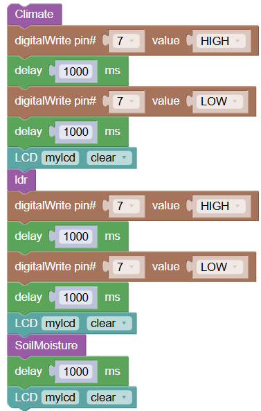
The Main Loop
•
Call temp_humid, ldr, and soil_moisture.
•
Time Limit: Give each function an 5-second time limit (Delay) followed by an LCD Clear block. This ensures the data stays on the screen long enough to be read before moving to the next sensor.
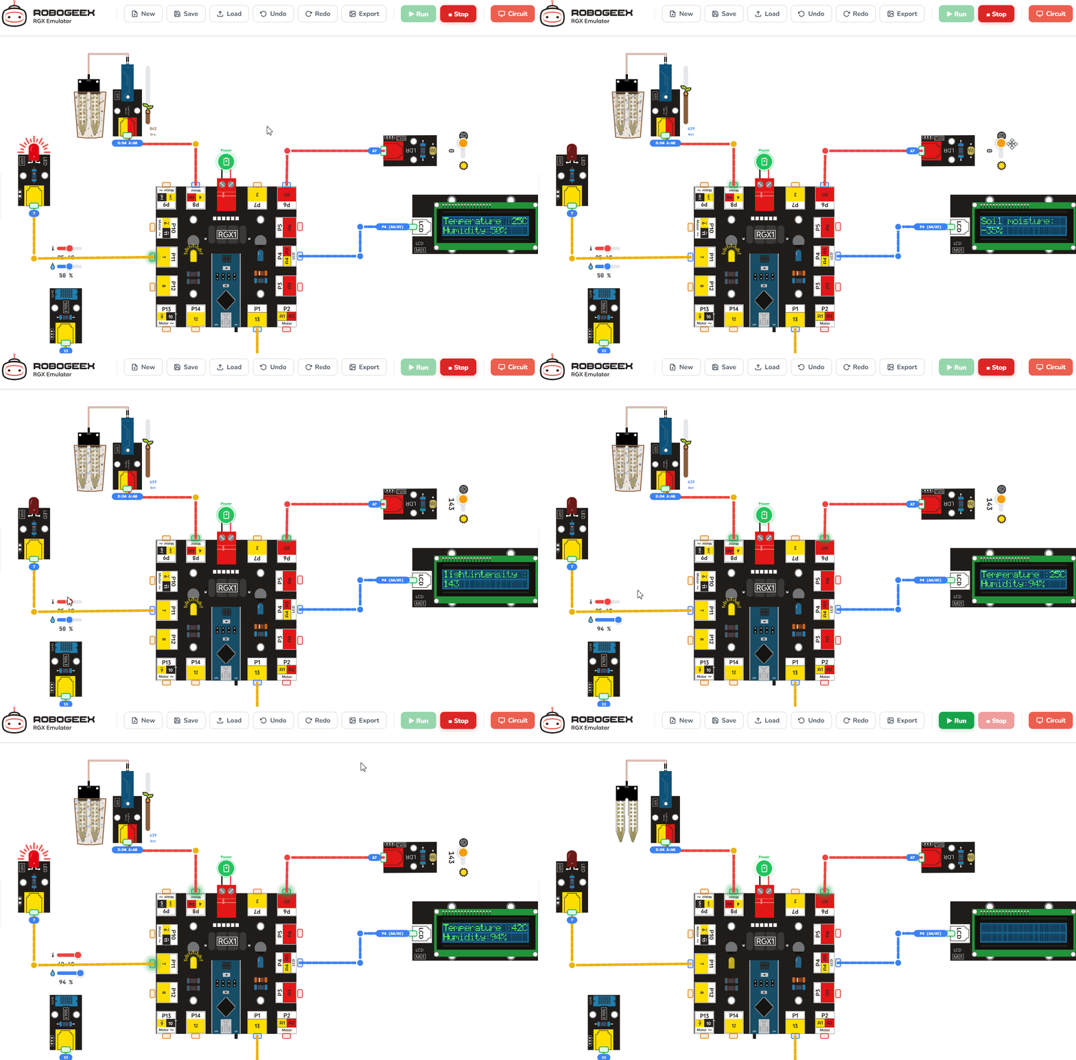
Running the code
Test Your System
1.
LCD Check: Does the screen show "Temp" first, then "Light," then "Soil"?
2.
Mapping Check: When the soil moisture sensor is dry, the mapped value should be low.
3.
LED Check: Does your LED on PIN 13 light up during the setup or when a specific function is called?
Improve & Extend
•
Water Alert: Inside the do soil_moisture function, add an IF block: if the moisture is low, turn ON the LED on PIN 13.
•
Smart Lighting: Inside the do ldr function, if the light is low (dark), turn ON the LED to act as a growth light.
•
Fast Refresh: Try reducing the delays to 2000ms to see the data update faster.