Overview
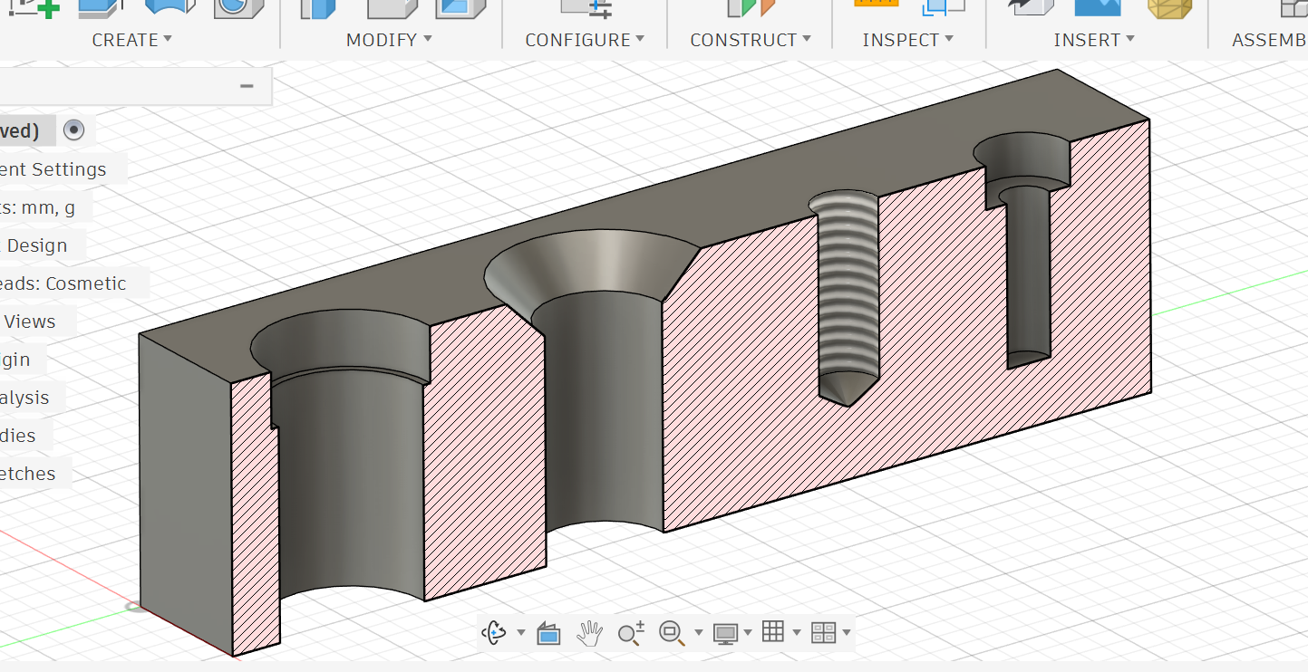
In this lesson, you will learn how to create different types of holes using the Hole feature. Instead of drawing circles manually and using Extrude Cut, the Hole tool gives you a more professional and parametric way to create standard holes for bolts, screws, counterbores, countersinks and threaded holes.
Objectives
By the end of this lesson, you will be able to
•
Understand the difference between simple holes, blind holes, through holes, counterbore holes, countersink holes and threaded holes.
•
Use the Hole command in Fusion 360.
•
Place holes accurately using sketch points and dimensions.
•
Create multiple holes using one Hole feature.
•
Read basic hole callouts from a technical drawing.
•
Apply counterbore dimensions such as hole diameter, counterbore diameter and counterbore depth.
Hole Types
Before creating holes in Fusion 360, it is important to understand why holes have different shapes. Different bolts and screws need different hole styles depending on their head shape.
Simple Hole
A simple hole is a straight cylindrical cut through or into the part.
It can be:
•
Through Hole: goes completely through the part.
•
Blind Hole: stops at a specific depth inside the part.
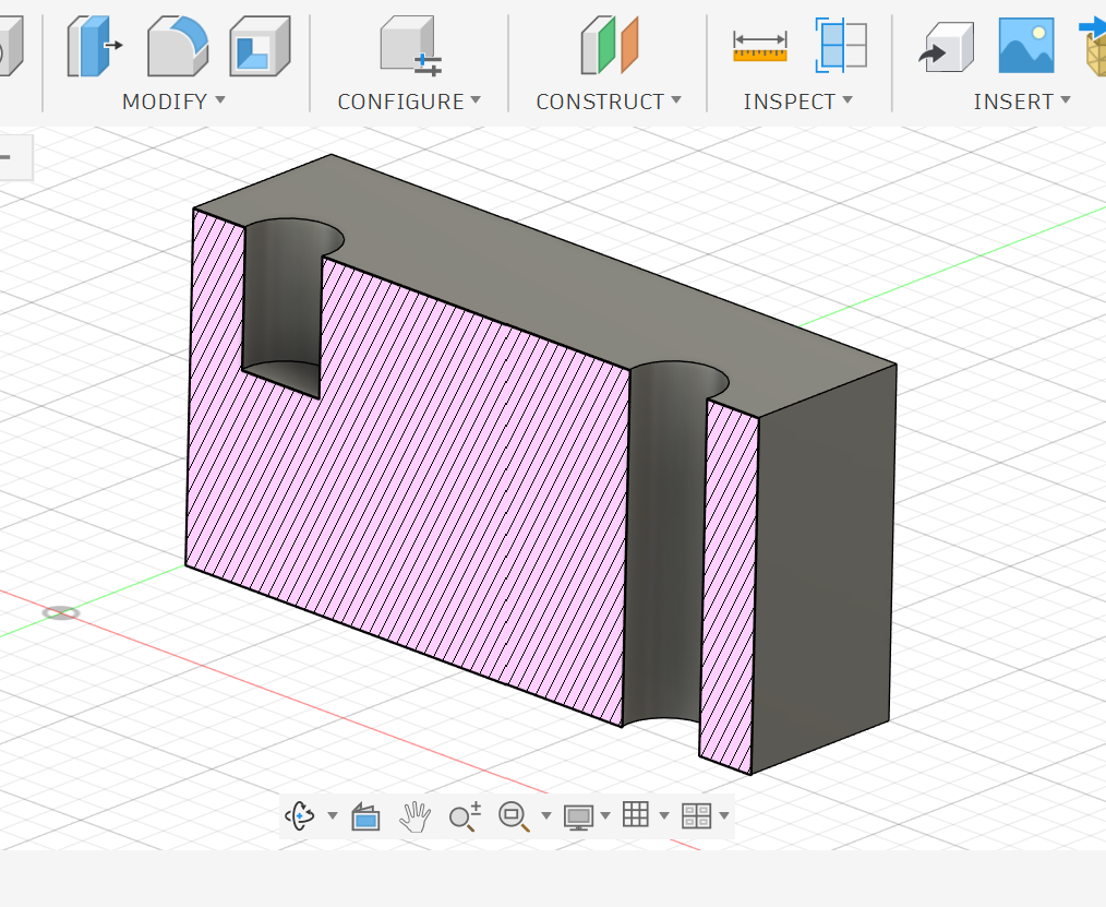
In drawings, a simple through hole may be written like:
Ø6 THRU
This means the hole diameter is 6 mm and it goes through the entire part.
Counterbore Hole
A counterbore hole has two diameters:
•
A smaller hole that usually goes through the part.
•
A larger flat-bottom recess at the top for the bolt head.
It is used when the screw or bolt head needs to sit inside the part instead of sticking out.
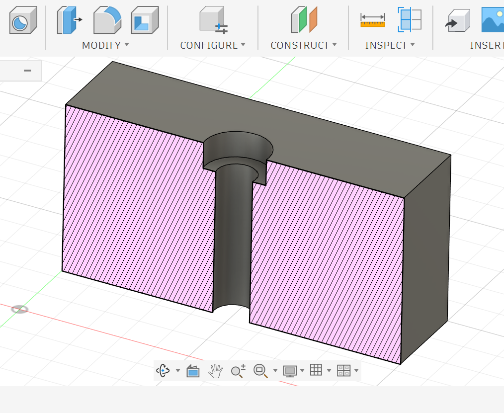
Example drawing callout:
Ø6 THRU ---> Create a 6 mm through hole.
Counterbore Ø12 depth 5 ---> Add a counterbore with 12 mm diameter and the counterbore depth is 5 mm.
2 PLCS ---> Repeat this for 2 places.
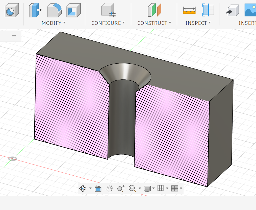
Countersink Hole
A countersink hole has an angled cone shape at the top. It is used with flat-head screws so the head becomes flush with the surface.
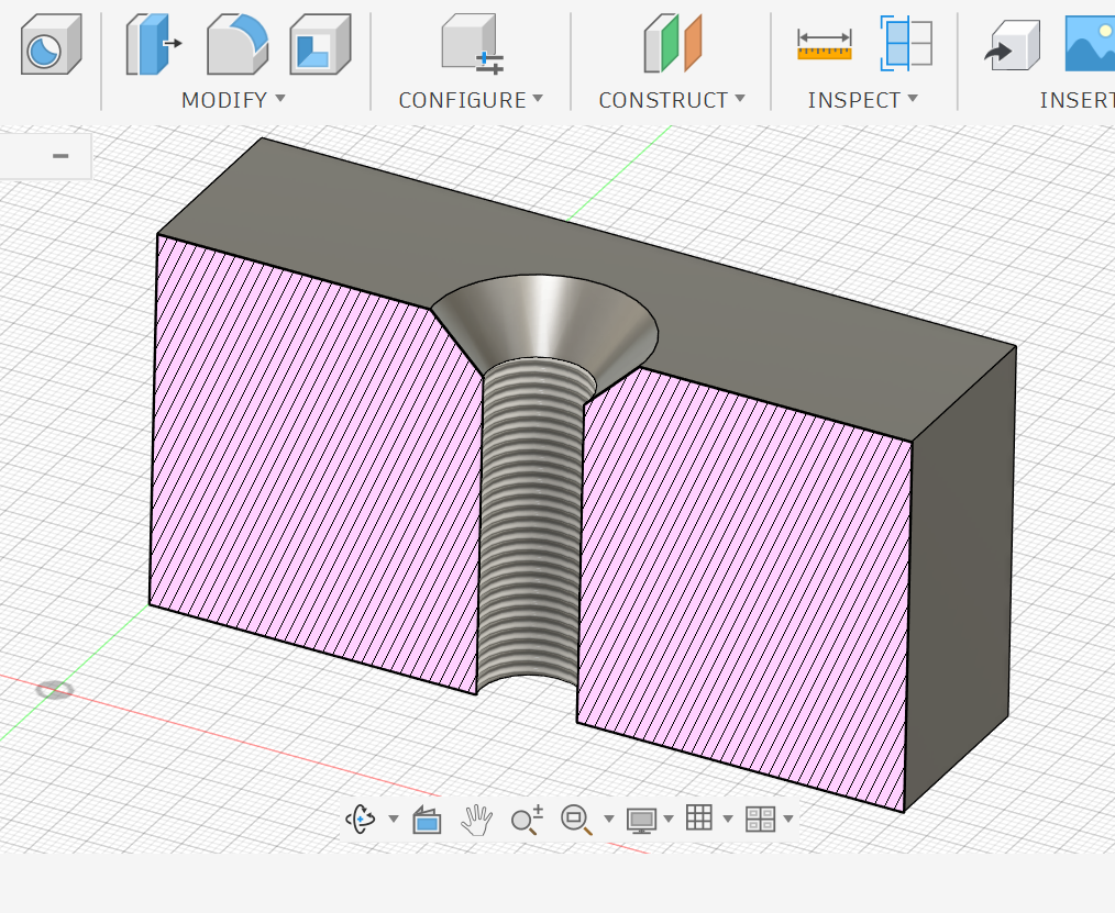
Threaded / Tapped Hole
A threaded hole contains internal threads so a screw or bolt can be tightened directly into the part. In Fusion 360, threaded holes can be shown as cosmetic threads or modeled threads.
Creating a Simple Hole
To practice the Hole tool, start with a simple rectangular block.
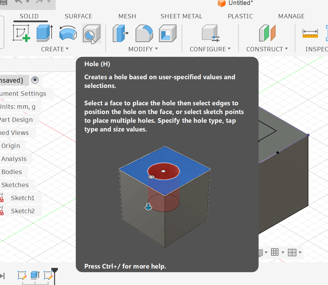
1. Create a Hole.
Go to Create --> Hole.
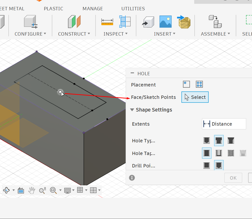
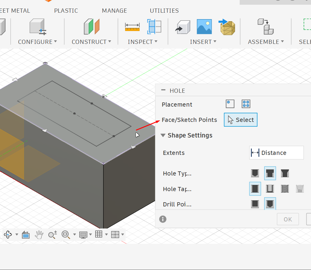
2.1. Use an Existing Sketch Point.
Alternatively, select a point from a previous sketch.
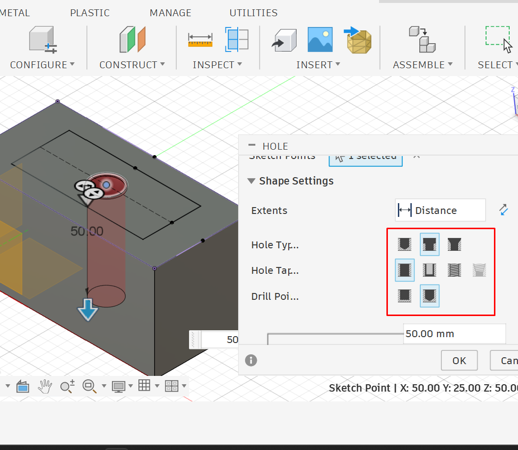
2. Set the Hole Placement.
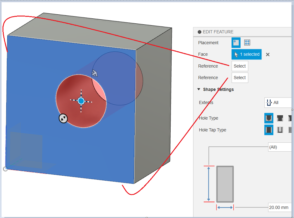
Select a face, then choose a reference.
3. Configure the Hole Type
Select the hole style, tap option and drill point.
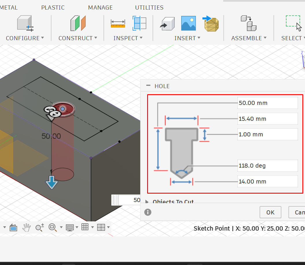
4. Enter the hole dimensions and depth.
Placing Holes Accurately
Do not place holes by eye. The correct method is to control the hole position using dimensions.
You can do this by:
1.
Creating a sketch on the face.
2.
Adding sketch points where the holes should be.
3.
Dimensioning the points from the edges.
4.
Finishing the sketch.
5.
Selecting the sketch points as hole positions.
This method is useful when you need more than one hole with the same size and type.
Multiple Holes in One Feature
If several holes have the same specifications, you can create them together.
1.
Create sketch points for all hole centers.
2.
Open the Hole command.
3.
Choose Sketch Points placement.
4.
Select all the points.
5.
Set the hole type, diameter and depth.
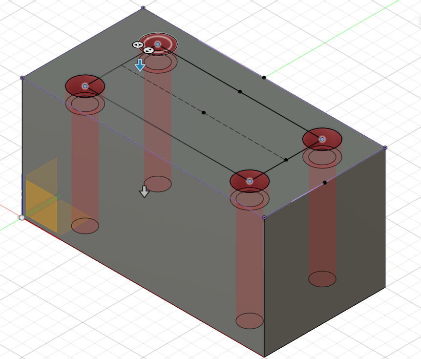
Fusion 360 will create all selected holes as one feature, making the model cleaner and easier to edit.
Important Notes
•
Use the Hole feature instead of manually sketching circles when the hole has standard engineering requirements.
•
Use Through All when the hole should always cut through the entire part.
•
Use sketch points to position holes accurately.
•
When a drawing says 2 PLCS, it means the same feature is repeated in two locations.
•
If Fusion 360 shows an over-constrained sketch warning, it means the sketch is already controlled by existing dimensions or constraints. Remove unnecessary dimensions or create a driven dimension only for reference.
•
Always read the hole callout carefully before creating the hole.
Practice Task
Create the mount bracket from the drawing and focus on making the holes correctly.
Your model should include:
•
The main bracket body.
•
The lower center cutout.
•
Two counterbore holes on the vertical face.
•
Hole size: Ø6 THRU
•
Counterbore: Ø12 depth 5
•
Top corner fillets: R6
•
Chamfers: 3 mm × 45°
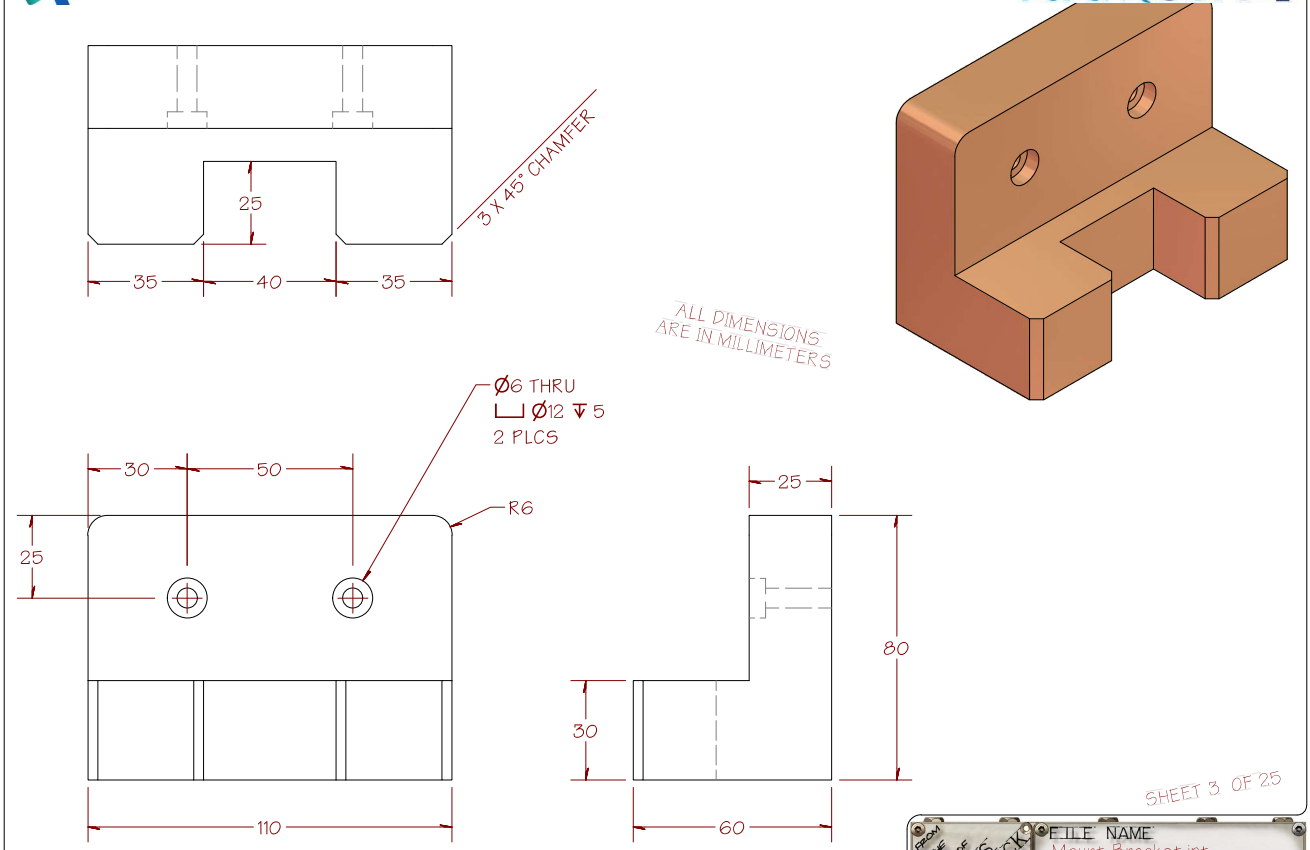
After finishing, edit the hole feature and change the counterbore depth from 5 mm to 7 mm. The model should update without needing to recreate the holes.
Reflection Questions
1.
Why is the Hole tool better than manually drawing circles and cutting them?
2.
What is the difference between a through hole and a blind hole?
3.
Why do we use a counterbore hole?
4.
What does 2 PLCS mean in an engineering drawing?
5.
Why should hole centers be controlled with dimensions instead of placed manually?
6.
What does Fusion 360 mean when it says the sketch is over-constrained?