Overview
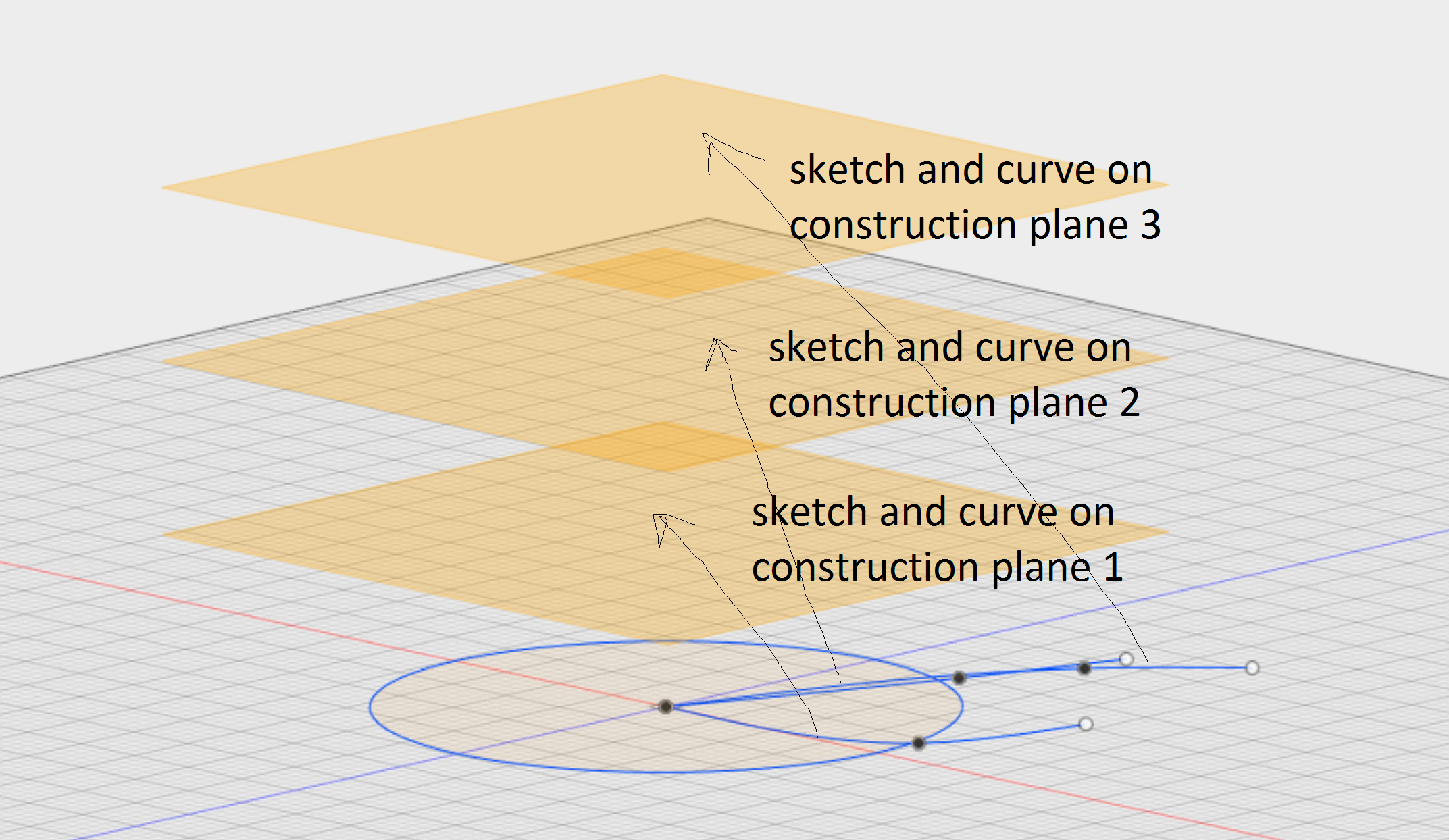
In this lesson, you will learn how to use Construction Planes in to create sketches in places where the default origin planes are not enough.
Objectives
By the end of this lesson, you will be able to
•
Understand what construction planes are used for.
•
Create new sketching planes away from the default origin planes.
•
Use construction planes to control the position and angle of sketches.
•
Choose the correct construction plane type depending on the design need.
•
Create features such as extrudes, cuts, holes or profiles using custom planes.
What are Construction Planes?
A construction plane is a temporary reference surface used to create sketches or features in a specific location.
It is useful when:
•
You need to sketch above or below an existing face.
•
You want to create a sketch between two faces.
•
You need a sketch at an angle.
•
You want to create a feature on a curved or slanted part.
•
The default origin planes are not in the needed position.
Offset Plane
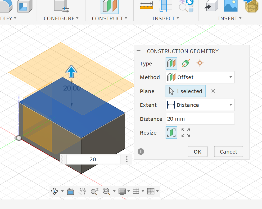
The Offset Plane creates a new plane parallel to an existing face or plane.
Use it when you want to sketch at a specific distance from a face.
Example uses:
•
Creating a sketch above a surface.
•
Placing a feature away from the main body.
•
Making repeated levels or layers in a design.
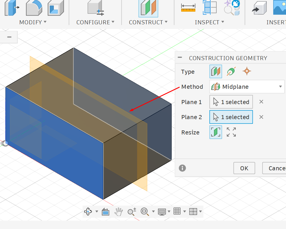
Midplane
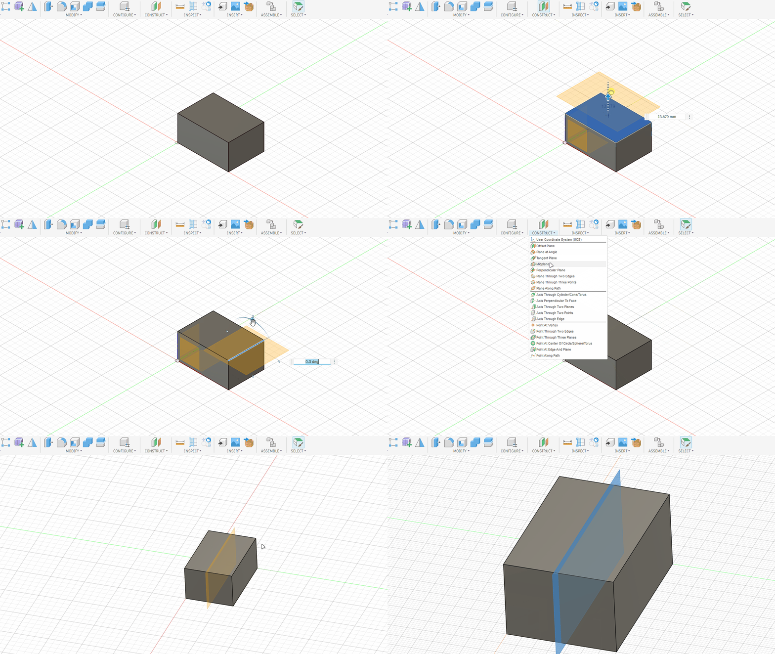
The Midplane creates a plane exactly between two selected faces.
Use it when you want a sketch or feature to be centered between two sides.
Example uses:
•
Creating symmetrical designs.
•
Sketching in the middle of a block.
•
Placing holes or cuts at the center of an object.
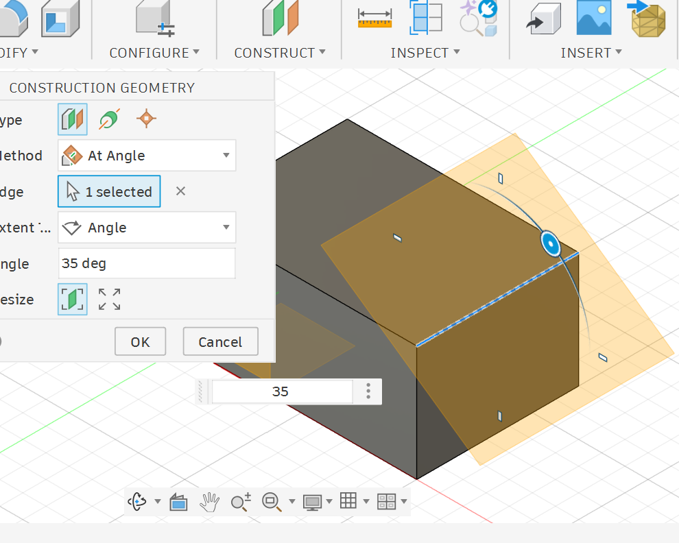
Plane at Angle
The Plane at Angle creates a plane rotated around an edge or axis.
Use it when you need to sketch on an angled surface or create angled features.
Example uses:
•
Angled cuts.
•
Slanted supports.
•
Tilted holes.
•
Ramps or inclined parts.
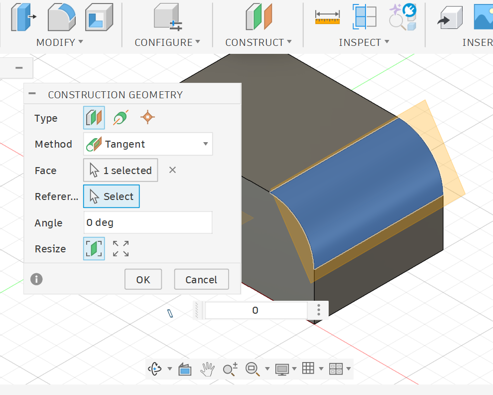
Tangent Plane
The Tangent Plane creates a plane that touches a curved surface.
Use it when working with cylinders, rounded bodies, or curved faces.
Example uses:
•
Sketching on a cylinder.
•
Creating holes or labels on curved surfaces.
•
Adding features to rounded objects.
General Workflow
A good workflow for using construction planes is
1.
Create or open the 3D body.
2.
Decide where the new sketch needs to be placed.
3.
Choose the correct construction plane tool.
4.
Select the required face, edge, point or path.
5.
Set the distance, angle or position.
6.
Create the construction plane.
7.
Start a new sketch on that plane.
8.
Use the sketch to create a feature such as Extrude, Cut, Hole, Revolve or Sweep.
Important Notes
•
Construction planes are not solid bodies.
•
They are reference geometry only.
•
You can hide or show them from the Browser.
•
You can rename construction planes to keep your design organized.
•
Always check that you are sketching on the correct plane before drawing.
•
If a plane appears on the wrong side, change the direction or use a negative value.
Common Mistakes
•
Creating the plane but forgetting to start the sketch on it.
•
Selecting the wrong face or edge as a reference.
•
Entering the distance in the wrong direction.
•
Using too many construction planes without naming them.
•
Trying to sketch in 3D space without a proper plane.
•
Forgetting to hide construction planes when the design becomes crowded.
Practice Task
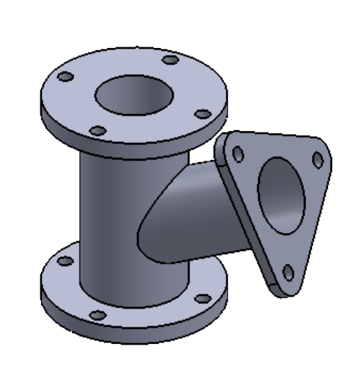
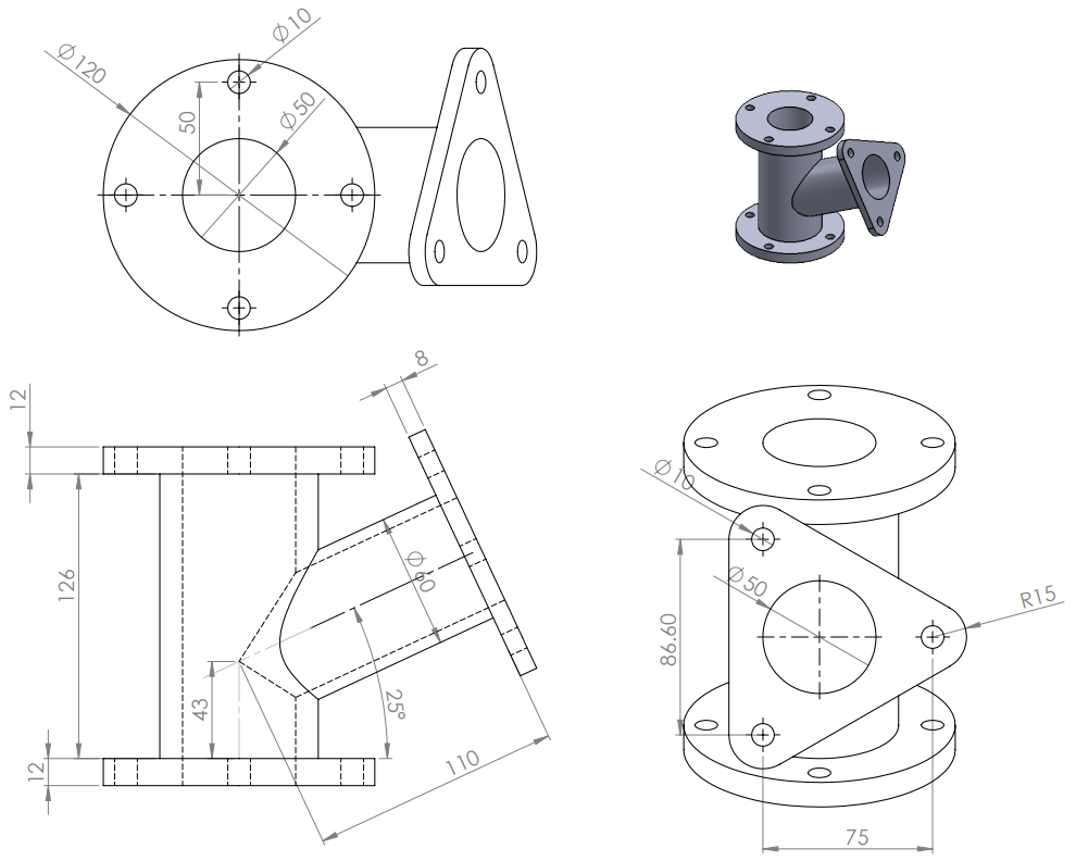
Create the mechanical part shown in the drawing.
You will model a part that contains a circular base, a raised cylindrical section, an angled side support and mounting holes. The goal is to practice creating sketches on different planes instead of using only the default origin planes.
Reflection Questions
1.
Why do we need construction planes in Fusion 360?
2.
What is the difference between an Offset Plane and a Midplane?
3.
When would you use Plane at Angle?
4.
Why is it important to select the correct reference face or edge?
5.
How can construction planes help when creating more complex 3D models?
6.
What happens if you sketch on the wrong plane?
7.
Which construction plane tool would you use before creating a Sweep feature?