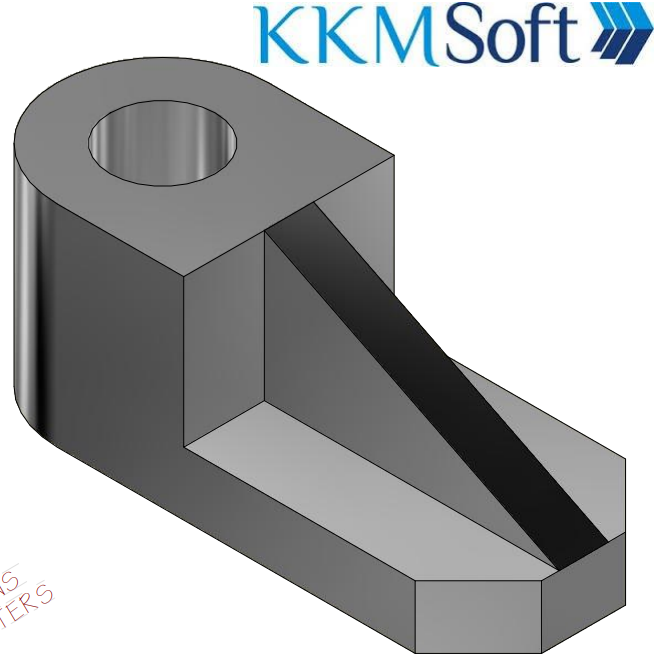
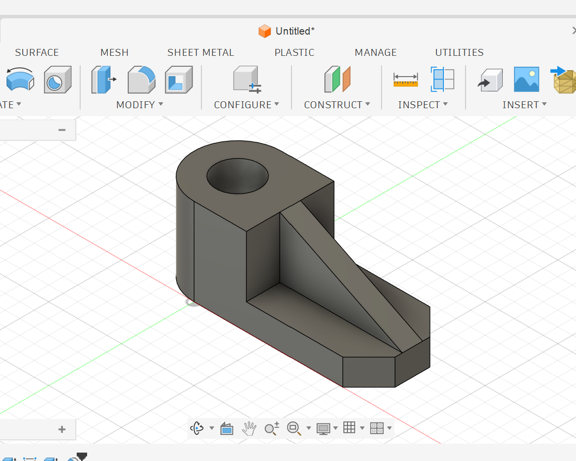
In this lesson, you will learn how to use the Chamfer feature in Autodesk Fusion 360 while modeling a mechanical fixture block. The model includes a rounded end, a hole, straight edges, chamfered corners, a recessed area and a sloped support rib. The goal is to understand how chamfers help remove sharp corners and create cleaner, more realistic mechanical parts.
Objectives
By the end of this lesson, you will be able to
•
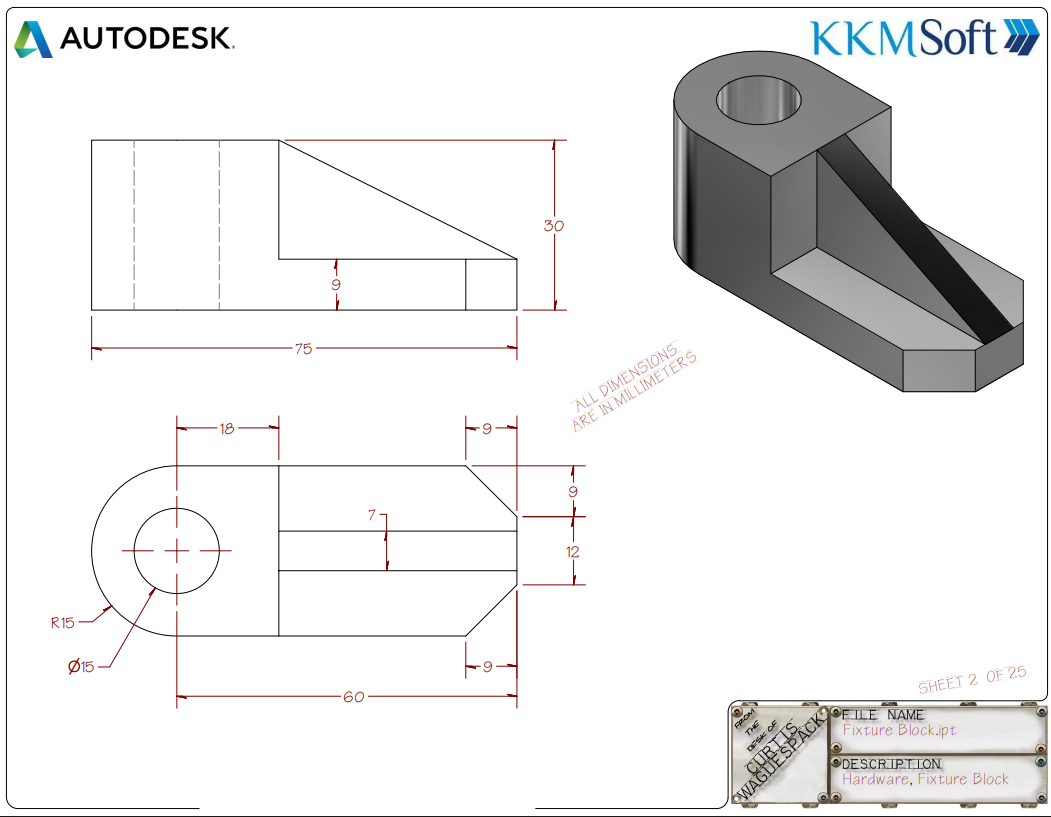
Read basic dimensions from a technical drawing.
•
Create a 2D sketch using rectangles, circles and lines.
•
Use the Chamfer tool to cut angled corners.
•
Create a sloped support shape using a side sketch.
Key Concept
What is a Chamfer?
A chamfer is a flat angled cut added to an edge or corner.
Instead of keeping a sharp 90-degree corner, a chamfer creates a slanted edge. This makes the part look cleaner and can also make it safer, easier to manufacture and more realistic.
In Fusion 360, chamfers can be used in two main ways:
1.
Sketch Chamfer: used while drawing a 2D sketch.
2.
3D Chamfer Feature: used on the edges of a 3D body.
Start a New Design
•
Open Autodesk Fusion 360 and create a new design.
•
Save the file with a clear name, for example:
•
Chamfer Feature Practice.
Saving early is important so you do not lose your progress.
Study the Technical Drawing
Before modeling, look carefully at the drawing.
The part contains:
•
A rounded circular end.
•
A hole through the rounded end.
•
A rectangular body.
•
Chamfered corners at the front.
•
A recessed middle area.
•
A sloped support rib.
•
A final chamfer on the front edge.
All dimensions are in millimeters.
Create the Main Top Sketch
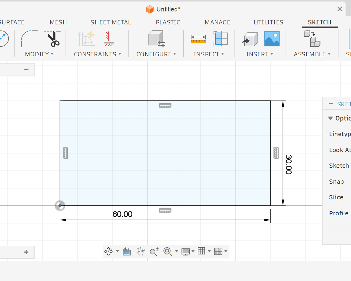
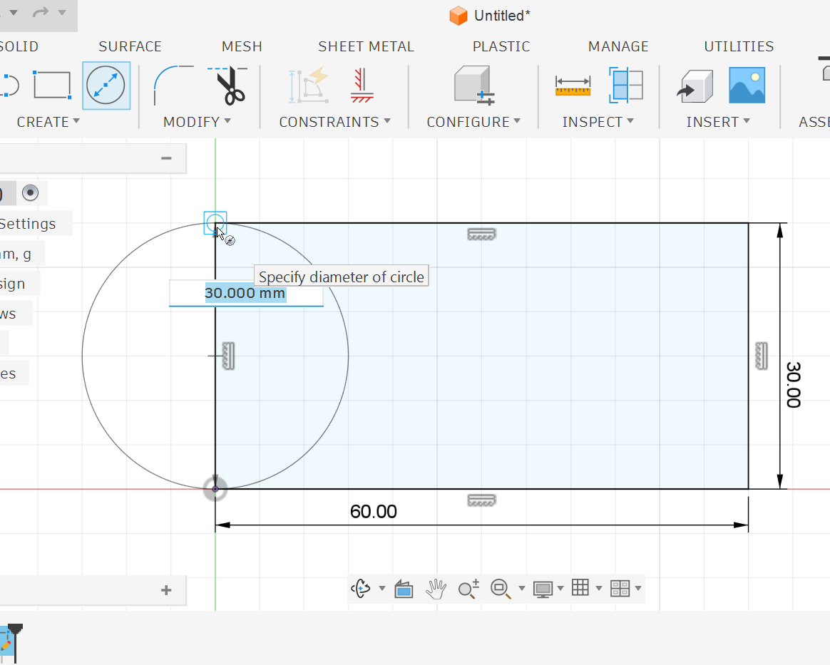
1. Start by sketching a rectangle with the correct width and height.
3. Drag to the rectangle’s corner until the snap marker appears.
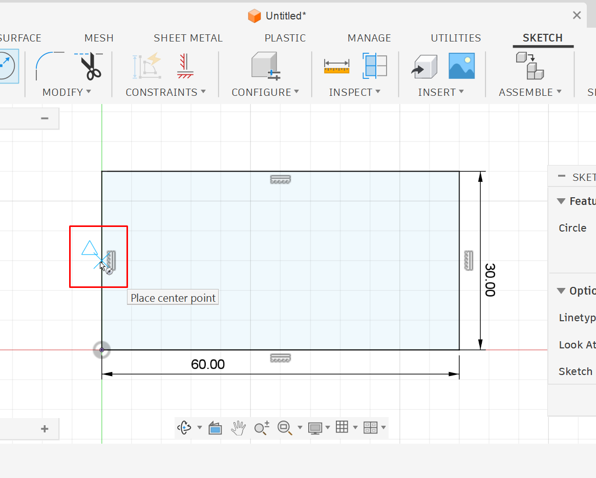
2. Place a circle in the center. The blue triangle marks the midpoint of the line.
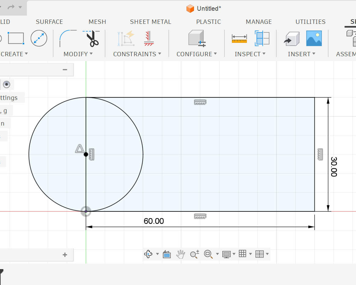
4. The circle is fully defined because its diameter matches the rectangle’s height.
Add the Hole
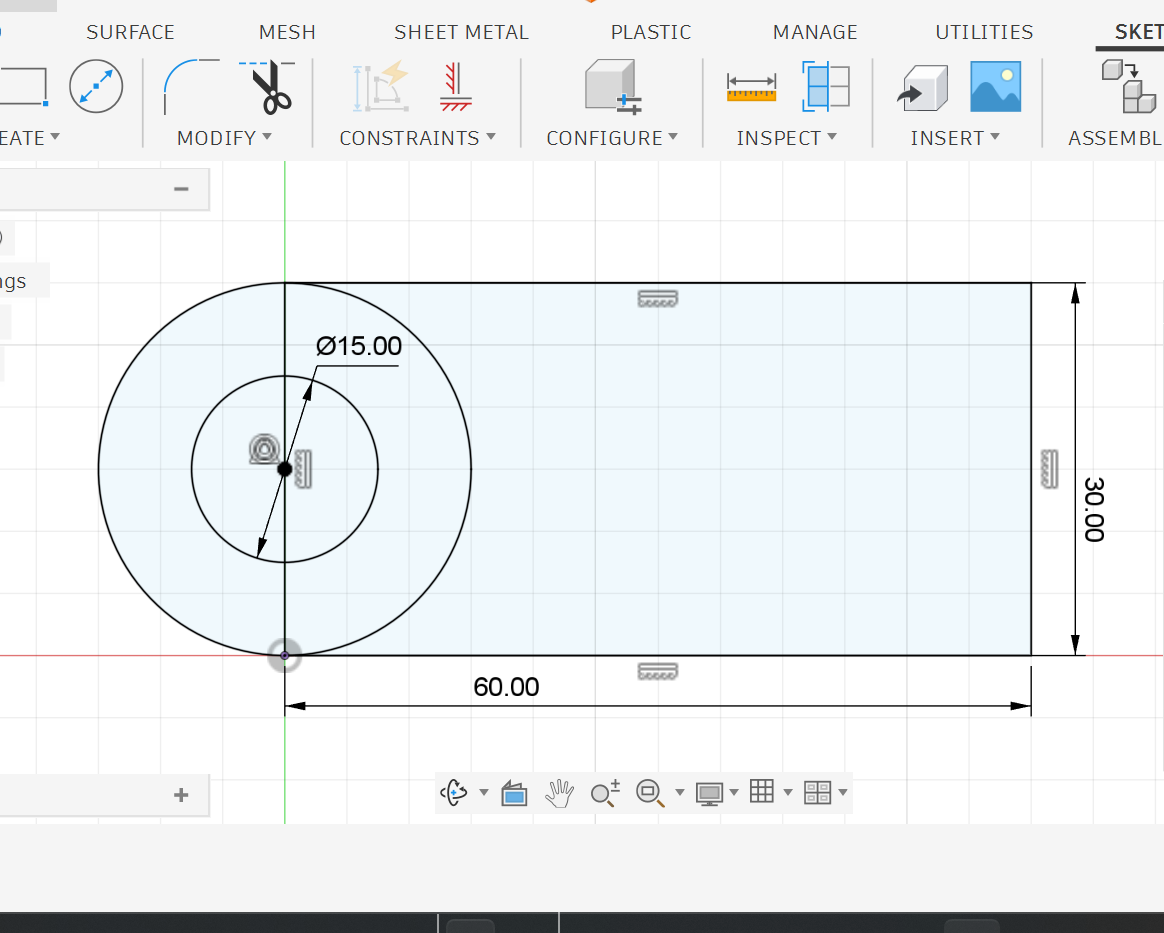
•
Draw another circle inside the rounded end.
•
This circle represents the hole in the part.
•
Set the hole diameter to: Ø15 mm.
•
Make sure the hole is centered correctly inside the rounded end.
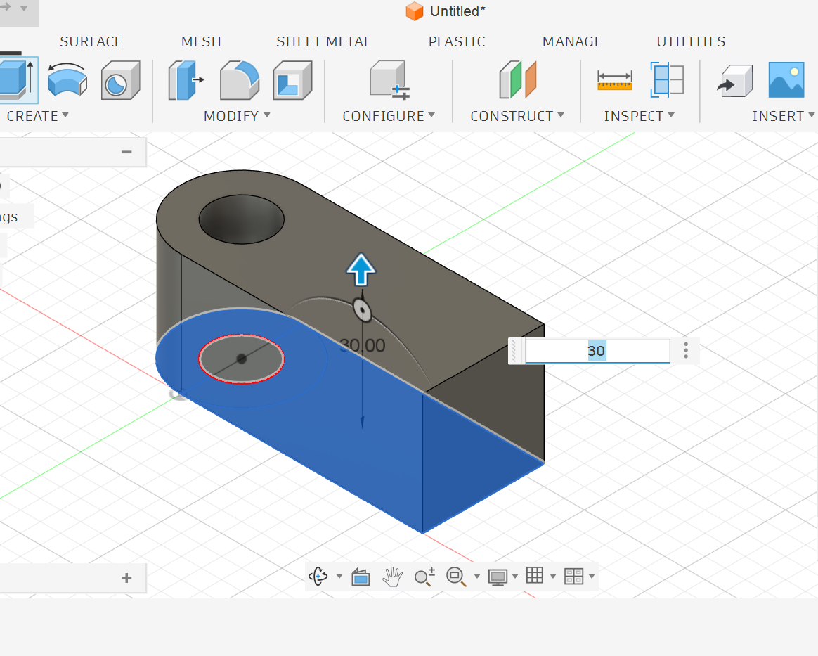
Extrude
Create the Recessed Area
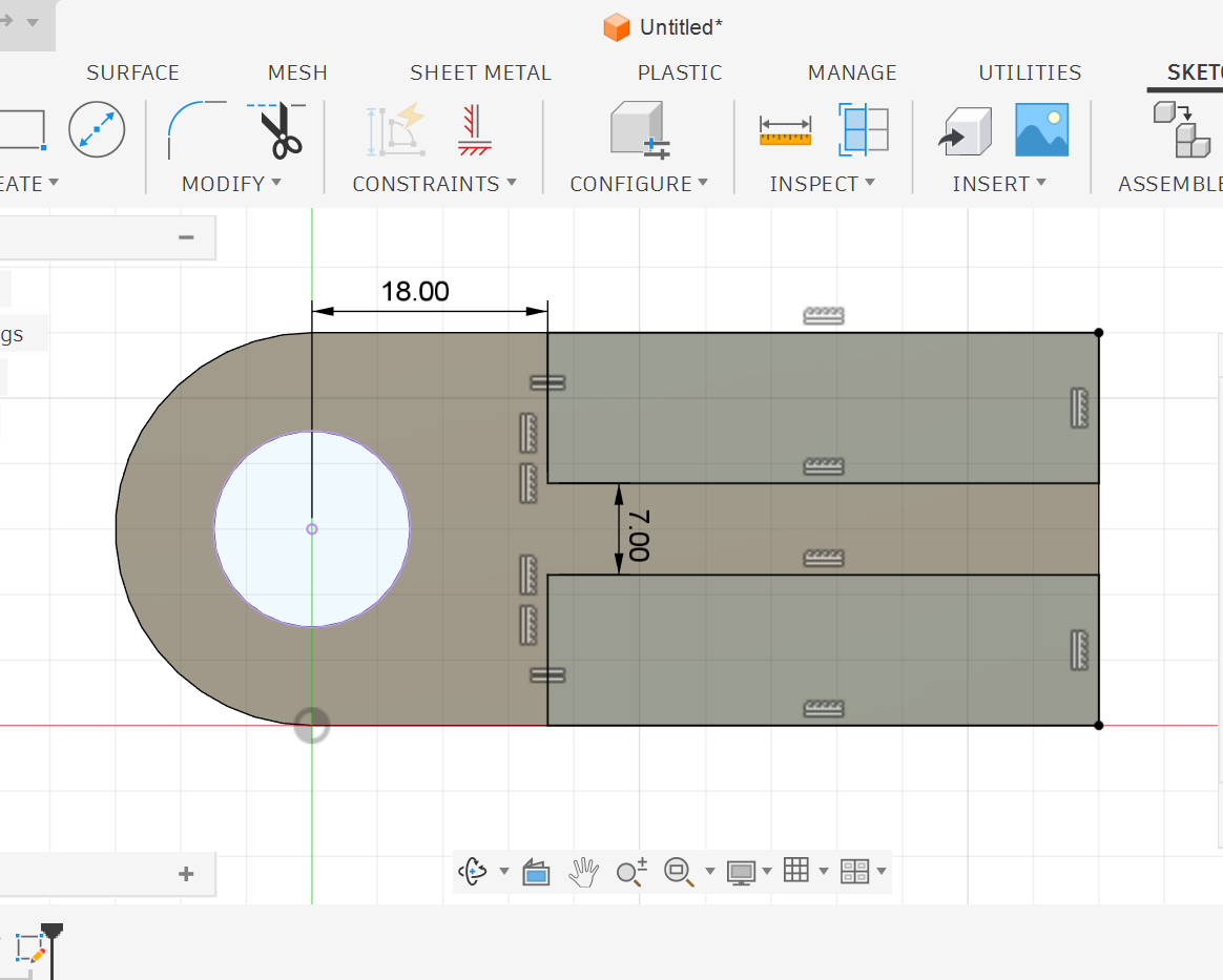
Draw the inner line s that define the recessed area and the center rib.
1. Refer to the image and apply the required sketch constraints accordingly.
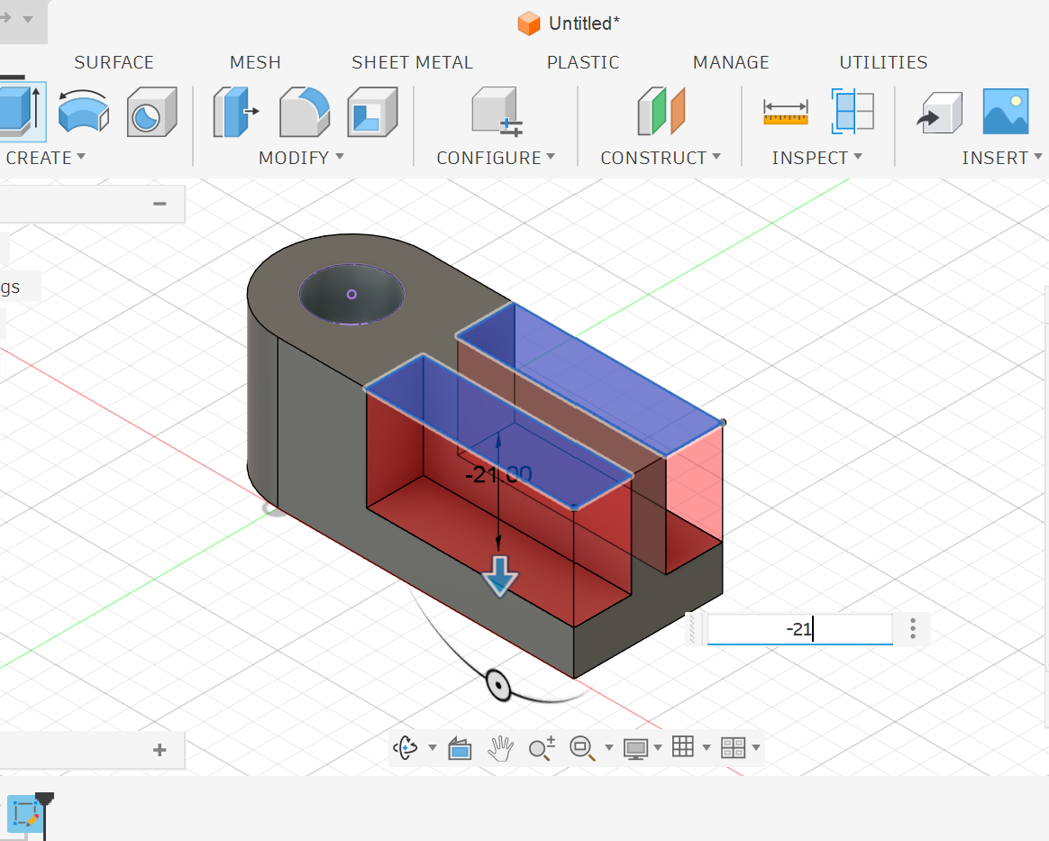
2. Use Extrude Cut according to the dimensions shown in the drawing.
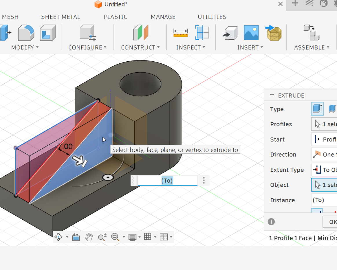
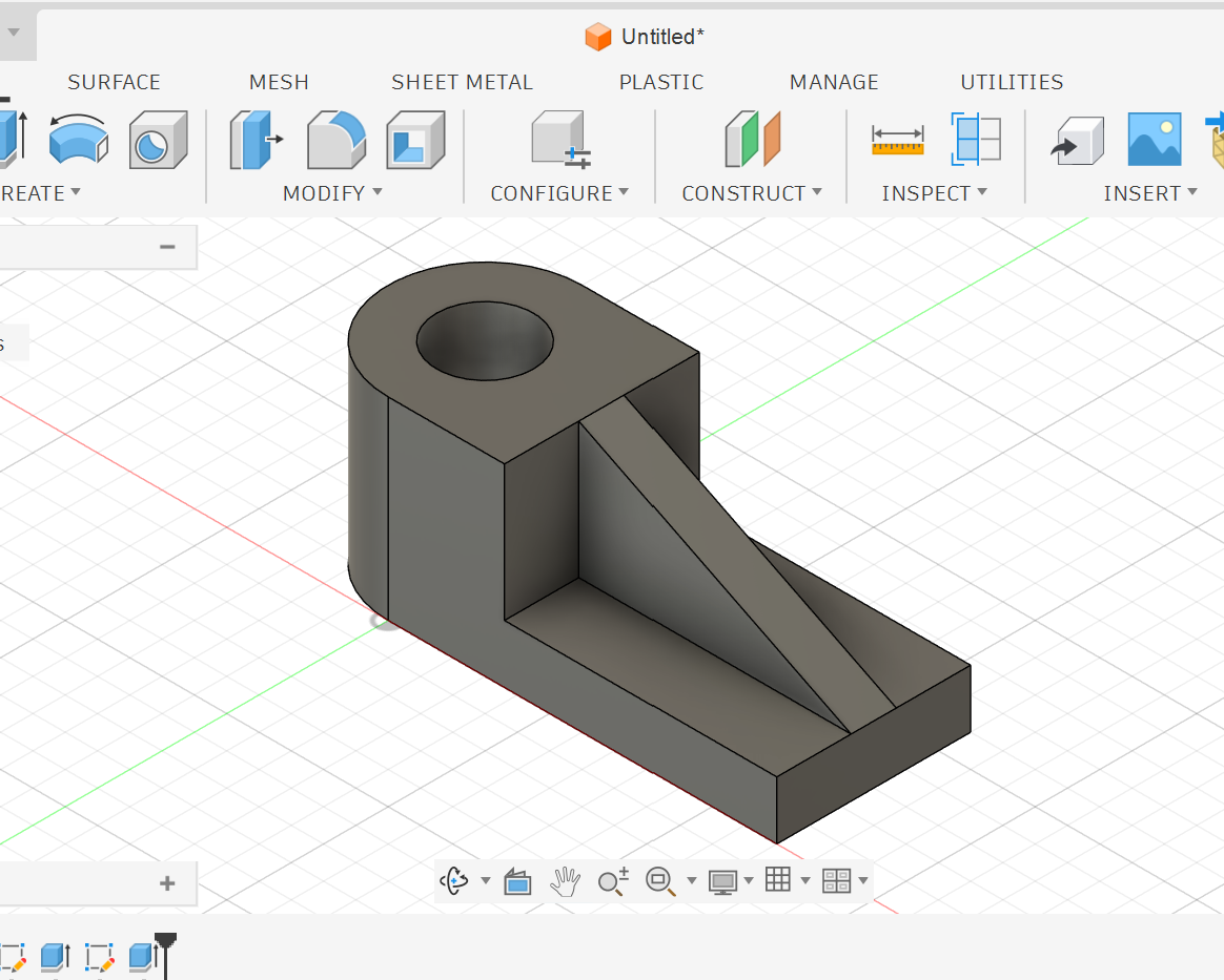
Create the Sloped Support Rib
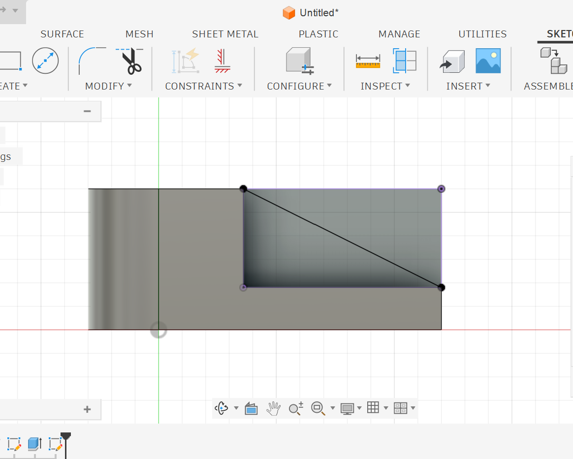
Create another sketch on the side face of the model.
1. Draw a diagonal line from the upper rear area down toward the front lower area.
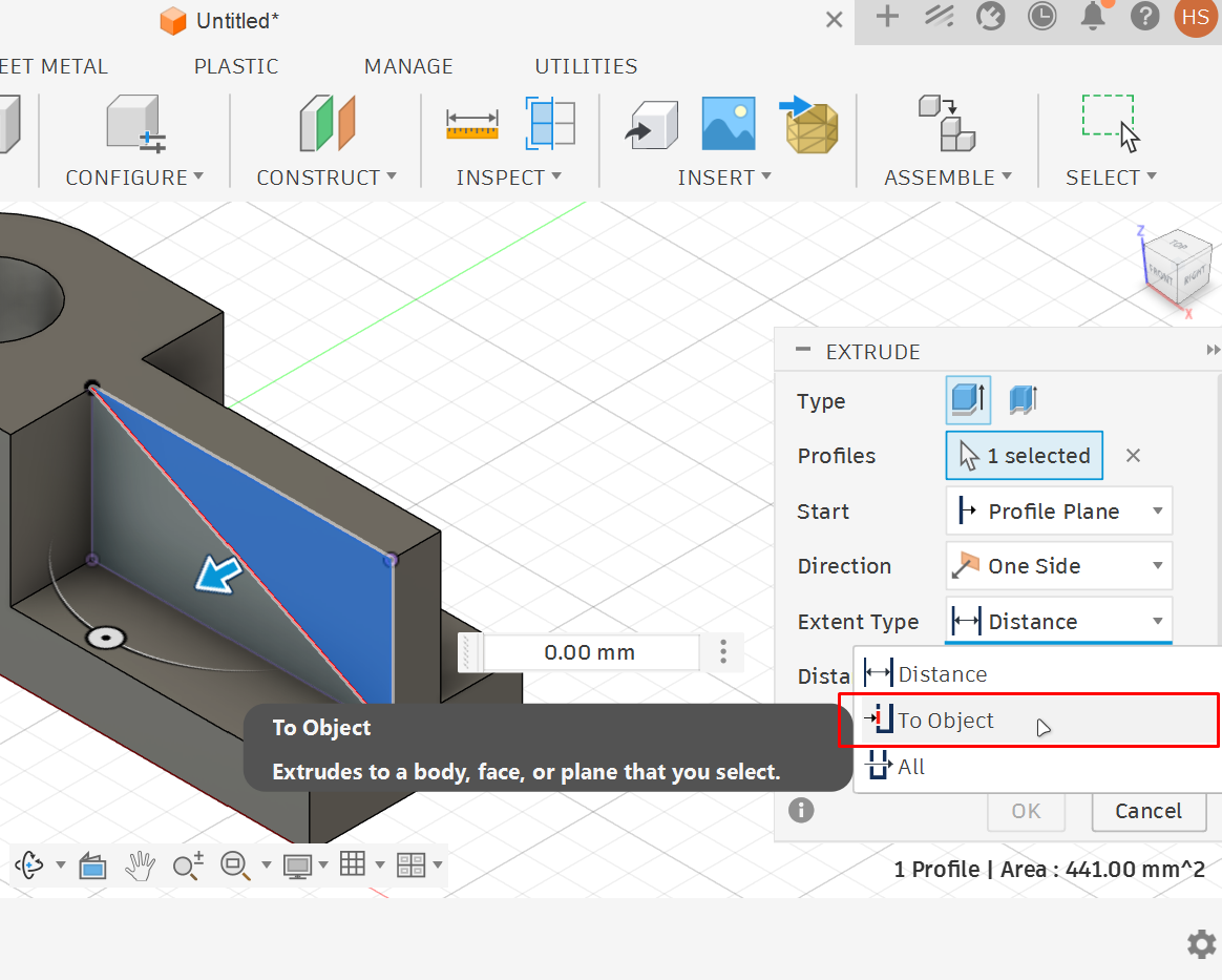
3. Select the opposite face as the target object for the cut.
2. Select the triangular profile, then set the Extent Type to To Object.
Success
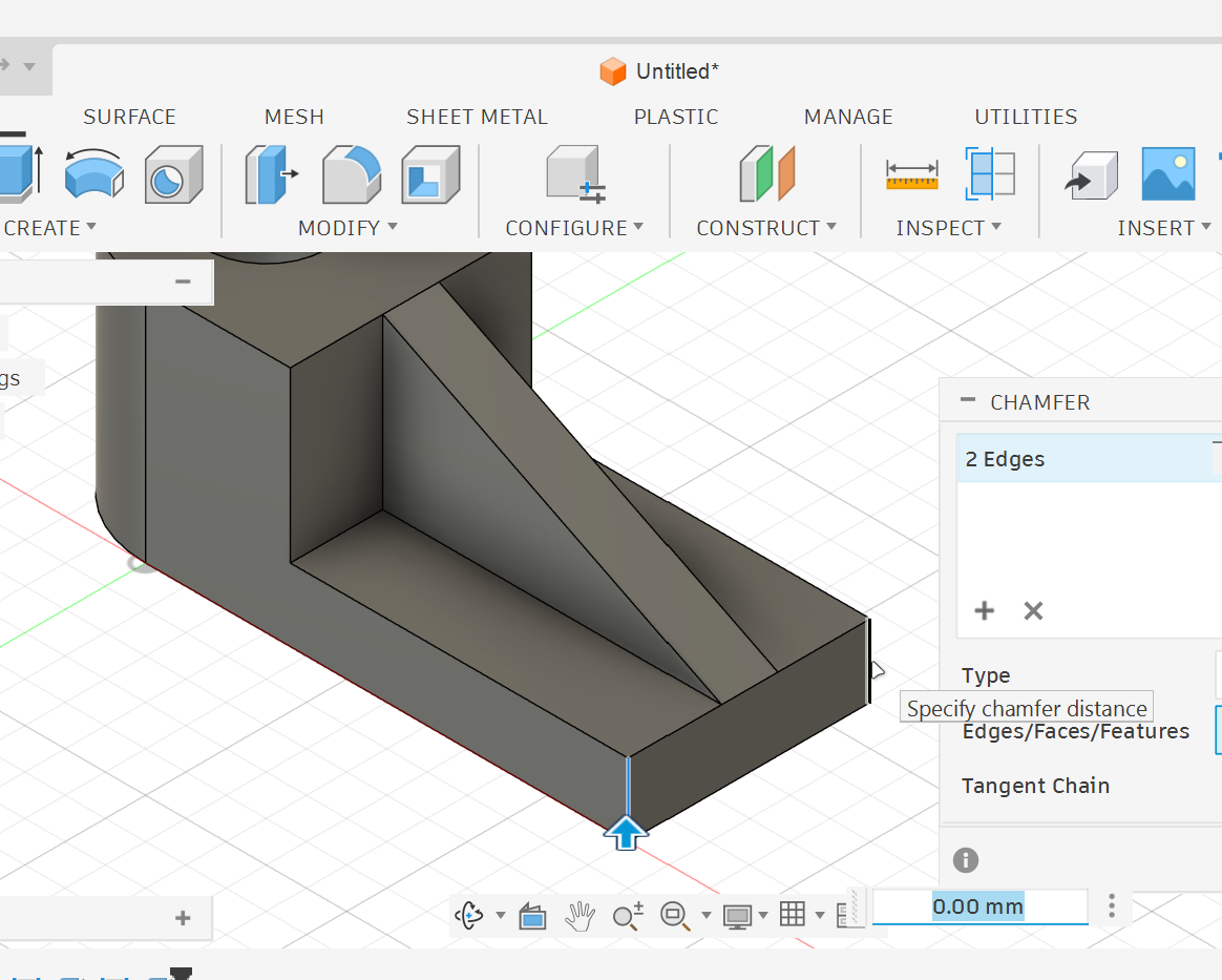
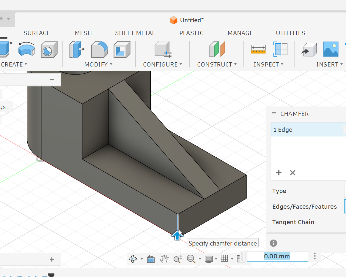
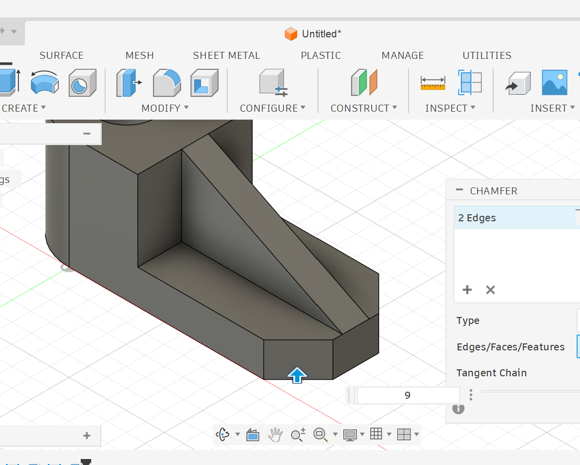
Apply the 3D Chamfer Feature
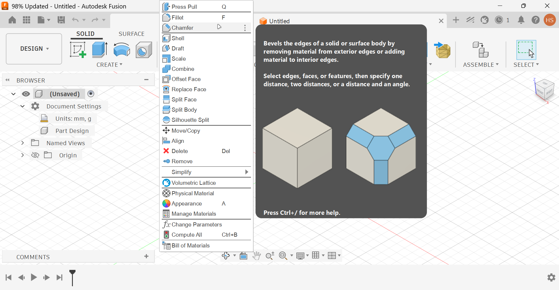
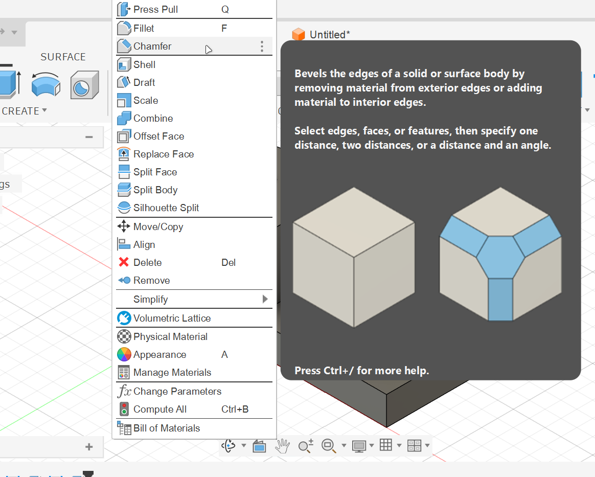
Now use the Chamfer feature from the Solid workspace.
1. Select the Chamfer tool.
3. Select the second front edge to apply the chamfer on both sides.
2. Select the first front edge.
4. Enter the required chamfer distance and confirm the result.
Success
The chamfer removes the sharp edge and creates a clean angled face.
Common Mistakes to Avoid
•
Forgetting to center the hole.
•
Selecting the wrong sketch profile during Extrude.
•
Cutting in the wrong direction during Extrude Cut.
•
Leaving extra sketch lines that create unwanted profiles.
Practice Task
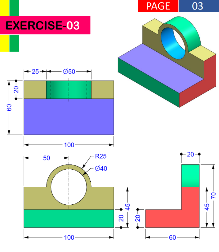
Create the part shown in the drawing. Use the given dimensions carefully and build the model using sketches and features.
Your model should include:
•
A rectangular base.
•
A raised back support.
•
A circular ring on top of the support.
•
A through hole inside the ring.
•
Correct extrusion depths and heights.
Reflection Questions
1.
Why do engineers use chamfers in mechanical parts?
2.
What happens if a sketch profile is not closed before extrusion?
3.
Why is it important to use exact dimensions instead of drawing freely?
4.
How did the chamfer change the shape of the front side of the model?